
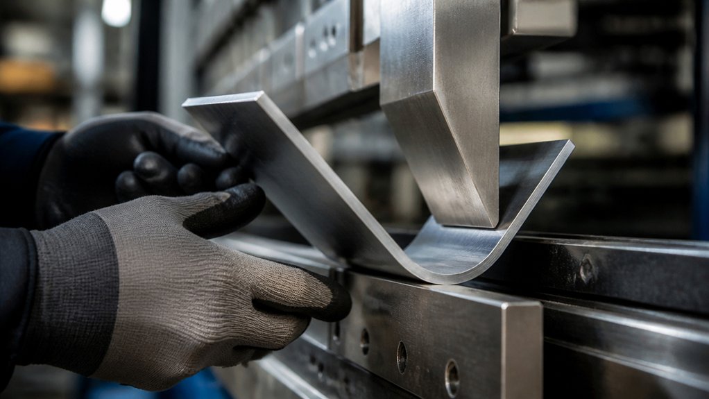
For a stainless-steel bracket, set the inside bend radius from the stainless grade and temper, sheet thickness, grain direction, and forming process—not from a mild-steel design. The inside bend radius is the radius on the inside face of the fold. A radius that is too tight can crack the material, especially when the bend crosses the rolling direction or the sheet is in a harder temper.
For press-brake forming, ask the fabricator to confirm the proposed radius against the material supplier’s forming guidance and the tooling available. The minimum practical radius depends on the specific grade, thickness, and bend setup, so a single value does not suit every stainless part. If the drawing allows a larger radius, that can reduce cracking risk, but it may affect fit and clearance.
The K-factor estimates where the sheet’s neutral axis—the layer that neither stretches nor compresses—lies during bending. It is used to calculate bend allowance, the length of material consumed by the bend, and therefore the flat-pattern dimensions. Because the K-factor varies with material and forming conditions, the production engineer should confirm it with the fabricator’s bend data or a sample bend, then check the resulting part against the drawing.
Understand Bend Radius and K-Factor
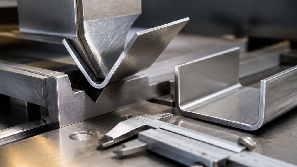
Bend radius and K-factor help determine the flat pattern for a sheet-metal bend. The inside bend radius is the radius of the curve on the inside face of the formed part. The K-factor describes the neutral axis—the layer of material that neither stretches nor compresses—as a fraction of the sheet thickness.
Together, these values determine bend allowance: the length of sheet used by the bend. For example, a production engineer specifying a 0.060-inch (1.52 mm) 304 stainless steel part should provide the material grade and thickness, the required inside radius, and the K-factor or the source used to establish it. The correct K-factor depends on the material, thickness, tooling, and forming process, so it shouldn’t be treated as a universal value.
When reviewing a flat pattern, check that its bend allowance matches the specified material and forming method. Ask the fabricator to identify the assumptions used if the K-factor isn’t supplied. Incorrect inputs can shift flange dimensions and cause fit-up problems; the bend radius and forming conditions also affect strain in the material.
Choose a Bend Radius for Your Material
Choose an inside bend radius that the specified sheet metal grade and forming process can handle without cracking. The inside bend radius is the distance from the bend’s inner surface to its center. For air bending, where a press brake punch forms the sheet without pressing it fully against the die, the required radius depends on the material, thickness, tooling, and bend angle.
Use the material supplier’s minimum-radius guidance for the exact grade and temper, meaning its heat-treated condition. Then confirm the choice with a sample bend made from the specified stock and tooling. A radius close to the sheet thickness may suit some ductile grades, but it isn’t a universal rule; harder or less ductile material may need a larger radius.
Check the supplier’s yield strength, the stress at which permanent deformation begins, and elongation, a measure of how much the material stretches before breaking. Include grain direction in the drawing or purchase specification when it matters: bending across the grain can reduce cracking risk in some materials. Inspect the sample for cracks, distortion, and springback—the sheet’s tendency to partly return toward its original shape after forming. If defects occur, revise the radius or forming method before production.
Calculate Bend Allowance With K-Factor
Calculate bend allowance with BA = θ(R + Kt), where BA is the length of material along the bend’s neutral axis, θ is the bend angle in radians, R is the inside bend radius, K is the K-factor, and t is the sheet thickness. The neutral axis is the layer of material that neither stretches nor compresses during bending. The K-factor expresses its position as a fraction of the thickness measured from the inside surface.
For a 90-degree bend, use θ = π/2 radians. For example, if a drawing specifies 0.125-inch (3.18 mm) sheet, enter that thickness and the specified inside radius in the formula; select K based on the material, temper or grade, and forming process. Air bending, bottoming, and coining can produce different results, so a K-factor from one setup may not suit another.
Use the calculated allowance when converting finished dimensions into a flat-pattern layout, following the drawing’s bend-dimension convention. Ask the fabricator to identify the assumed K-factor, inside radius, material specification, and forming method so the flat pattern can be checked against the intended part. A test bend or documented process data can help confirm the allowance; grain direction and bend radius also affect cracking risk.
Check Bend Designs for Cracks and Errors
Check a sheet-metal bend for cracking by comparing the inside bend radius with the alloy, temper, thickness, and forming process. The inside bend radius is the curve on the inner face of the bend; a radius that’s too small can stretch and split the outer face. For example, a bend in 5052-H32 aluminum may need a different radius from one in 304 stainless steel, so the material grade and temper should be stated on the drawing and checked against the material supplier’s forming guidance.
Inspect the bend line for nearby holes, slots, and edges, which can deform during forming or leave too little material to support the bend. Bend relief is a cut at the end of a bend where a flange meets it; it helps prevent tearing and material buildup, but its size depends on the sheet thickness and part geometry. Review the formed model for collisions, uneven flange lengths, and interference with adjacent features.
Check the flat pattern—the unfolded blank used to cut the part—for the outline, bend lines, relief cuts, and dimensions. Compare it with the bend allowance, the material length consumed by the bend, and the K-factor, a value used to locate the neutral axis where the material neither stretches nor compresses. If the pattern doesn’t match the specified part, revise the geometry or forming assumptions and regenerate it before release.
Frequently Asked Questions
How Does Grain Direction Affect Sheet Metal Bending?
For sheet-metal press-brake bending, bending across the rolling direction generally lowers the risk of cracking than bending along it, especially in less ductile alloys. The rolling direction is the direction in which the sheet was elongated during rolling; manufacturers often mark it on the material certificate or packaging.
The difference comes from the sheet’s grain structure and mechanical properties, which vary with rolling direction. Bending along the grain can make cracks more likely at the outside of the bend, where the material stretches. The result depends on the alloy, temper, thickness, bend radius, and condition of the material, so grain orientation alone does not determine whether a bend will succeed.
When preparing a drawing or purchase specification, identify the material grade and temper, sheet thickness, inside bend radius, and required bend direction relative to the rolling direction. If the part has tight bends or visible edges, specify that the supplier confirm orientation and qualify the setup with representative test coupons before production. Coupon results should be checked for cracking and dimensional fit; changing bend radius or orientation may be needed.
What Tools Are Needed to Measure a Bend Accurately?
Use a steel rule, calipers, an angle finder, and a radius gauge to check a formed bend against the part drawing. A steel rule checks overall dimensions; calipers measure feature sizes, such as flange length; an angle finder checks the bend angle; and a radius gauge compares the inside bend radius with the specified profile.
The right tools depend on the material, thickness, bend geometry, and required tolerances. For example, a radius gauge may not fit a tight bend or a small part, so the drawing may need to specify another inspection method. Confirm that the drawing identifies the measurement points and whether dimensions refer to the inside, outside, or centerline of the bend.
Check the flat blank dimensions before forming, then inspect the finished part. Compare the angle and inside radius with the drawing, and measure flange lengths from the stated reference surfaces. For repeat production, the buyer or engineer should also specify how many parts to inspect and what measurement method to use, based on the job’s quality requirements.
Can Sheet Metal Be Bent Without a Press Brake?
Yes, sheet metal can be bent without a press brake, especially for simple parts made from thin, ductile material. The suitable method depends on the alloy, thickness, bend length, bend radius, and required accuracy.
For a short bend in mild steel or aluminum sheet, a vise and clamps can hold the work while a mallet forms the bend. A folding bar—a clamping tool that grips the sheet along the bend line—can produce a straighter fold. A hand seamer, a plier-like tool for forming sheet edges, is useful for short flanges. Rollers form curves rather than sharp bends.
These methods offer less control over bend angle and consistency than a press brake, a machine that forms bends with a punch and die. They may be unsuitable for long parts, tight radii, thick sheet, or jobs with close dimensional tolerances. Check the material specification and thickness, then make a sample bend to assess cracking, springback—the material’s tendency to partly return toward its original shape—and dimensional accuracy. For repeat production, the required consistency and setup time may favor a press brake or another controlled forming process.
How Should Finished Bent Parts Be Stored?
Store finished bent parts in a dry, clean area, supported to prevent sagging or distortion, and separated to avoid scratches and dents. The right support and separation method depends on the part’s material, shape, finish, and weight.
For carbon-steel parts, keep moisture and condensation away to reduce corrosion; use a suitable protective coating when the storage period or environment requires it. Stainless steel and aluminum can also be damaged by contamination or contact with other materials, so use clean supports and separators compatible with the specified alloy and finish. Do not stack parts unless the lower pieces can carry the load without bending or marking.
Use padded racks, dividers, or non-abrasive separators where contact could damage a finished surface. Support long or thin parts at enough points to limit sagging, and avoid pressure on flanges or bends that could change their shape. Follow the drawing’s grain-direction requirements when orienting parts; grain direction refers to the direction of the sheet’s rolling pattern and can affect appearance and forming behavior.
Before shipment or assembly, check critical dimensions against the drawing with suitable measuring tools. Agree on storage and handling requirements in the purchase specification when finish, geometry, or storage duration makes damage especially consequential.
When Should a Design Use Multiple Bends Instead of One?
Use multiple bends when a single bend in sheet metal cannot create the required profile, provide the needed stiffness, or fit around nearby parts. A bend is a change in direction formed in a sheet; each additional bend can create a flange, channel, or offset, but also adds another feature to control.
For example, a channel-shaped part needs two bends, while a box-like profile may need several. On a bracket made from 304 stainless steel sheet, the bend sequence can affect whether the press brake’s punch and die can reach each feature without hitting a flange already formed. A press brake is a machine that forms sheet metal between a punch and a die.
Before issuing a drawing, show the bend sequence and identify the material grade and thickness. Check tool access, flange clearance, and how the part will be supported during forming. The right sequence depends on the profile, tooling, and production method.
Multiple bends can stiffen a part or help it fit an assembly, but they can also increase springback—the sheet’s tendency to partly return toward its original shape after forming. Specify critical dimensions and tolerances on the drawing, and confirm them with the fabricator before production. The material, thickness, bend geometry, and measurement method all affect what tolerances are practical.