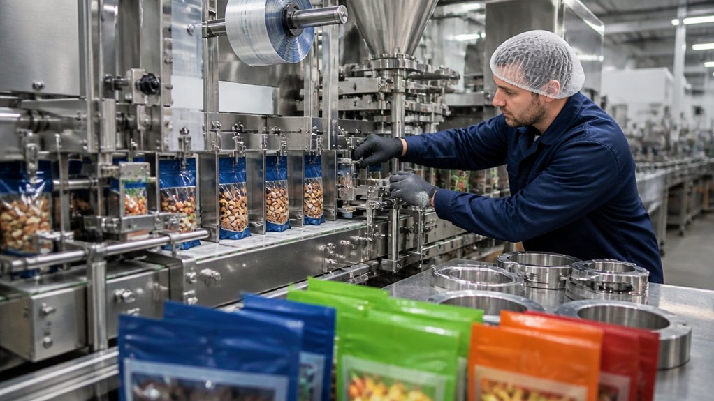
A flexible packaging line can switch from a family-size pouch to a single-serve package faster when changeover tasks are planned, standardized, and checked before production stops. The same principle applies to metal fabrication: define the part, material, and finish before work begins, then make sure the drawing and inspection plan match.
For a sheet-metal enclosure, specify the alloy and temper, such as 5052-H32 aluminum, and give the sheet thickness in inches (millimetres). Identify the forming and joining processes, such as press-brake bending and TIG welding, and mark bend locations, welds, and finished dimensions on the drawing. Add tolerances only where fit or function requires them; suitable limits depend on the part geometry, material, and process.
A clear work package can reduce delays caused by missing information or tooling changes. Include the revision-controlled drawing, material requirements, surface-finish expectations, and inspection points. For repeat orders, confirm that the supplier can retain or reproduce the required fixtures and setup instructions.
Check the first completed part against the drawing before approving a full run. Record any deviations and agree on how they will be resolved before production continues.
Find the Biggest SKU Changeover Bottlenecks
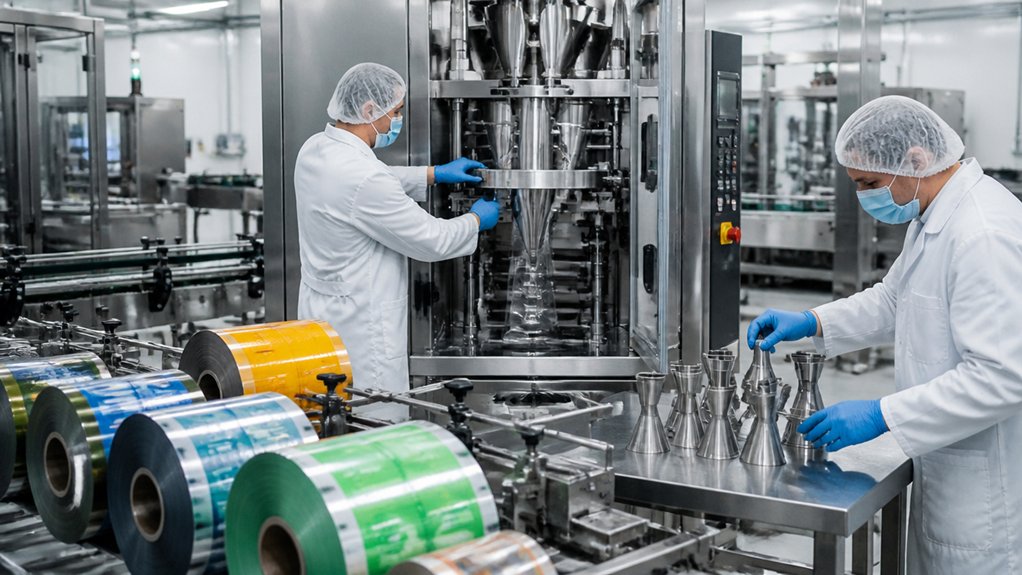
The biggest changeover bottlenecks in metal fabrication are the steps that repeatedly delay a job moving from one part or setup to the next. Track time from the last accepted part in one run to the first accepted part in the next, and record each delay by task, machine, and operator. Separate planned setup from waiting, rework, inspection, and approval.
> Track each changeover delay by task, machine, and operator, separating planned setup from waiting, rework, inspection, and approval.
Group jobs by process and material, such as laser-cut 304 stainless steel sheet, press-brake-formed A36 steel plate, or MIG-welded aluminum parts. MIG welding uses a wire electrode and shielding gas. Compare changes within each group and between groups; switching material, thickness, tooling, or weld procedure may require different setup work.
Use time studies and production records to find where delays cluster. Check material staging, tool changes, machine programming, fixture alignment, cleaning, and first-piece inspection. A fixture is a device that holds a part in position during machining or welding. Rank bottlenecks by lost production time and how often they occur, then investigate the highest-impact causes.
Review the records with operators and supervisors. They can identify hidden waits, repeated adjustments, or unclear drawings and specifications. Compare later jobs with the same baseline to see whether changes reduce delays without increasing defects. The best fix depends on the process, material, part geometry, and required inspection.
Prepare Flexible Equipment, Tooling, and Settings
Before a metal fabrication run ends, define the next part’s material, dimensions, process, and inspection requirements, then confirm that the planned tooling fits the machine.
For a sheet-metal part, the brief should identify the alloy and grade, thickness, bend locations, hole sizes, and required finish. State dimensions in inches with millimetres in brackets, and cite the drawing or governing specification for tolerances rather than assuming a shop standard.
List the required tooling and verify compatibility with the equipment’s capacity and setup. For press-brake forming, for example, specify the punch and die profile, material thickness, bend radius, and flange dimensions; the correct setup depends on the alloy, part geometry, and machine. For laser cutting, identify the material grade and thickness and confirm that the approved cutting program matches the drawing revision.
Provide the current drawing, material certificate requirements, and inspection points with the job package. A material certificate records the supplied metal’s grade and traceability. If an approved substitute is allowed, document its grade, thickness, and any required changes to cutting or forming settings. Record tooling condition and flag worn or damaged items before setup. Keep machine settings tied to the specific material and part, and require approval before operators change controlled dimensions or process parameters.
Run a Safe, Standardized SKU Changeover
For a metal-fabrication SKU changeover, stop the production line, isolate hazardous energy, and follow a documented sequence for clearing the previous job and setting up the next one. Hazardous-energy isolation means preventing unexpected startup or release of stored energy; specify the required lockout/tagout steps for the equipment and have trained personnel verify isolation before work begins.
The changeover checklist should identify the next part number, material grade, thickness, and approved drawing revision. For example, specify ASTM A36 carbon steel or 304 stainless steel only when the design or purchase specification calls for it. Confirm that sheet, bar, tooling, and consumables match the job, and remove leftover stock and parts from the prior run.
Set and verify the process parameters for the equipment in use, such as press-brake tooling and bend sequence or laser-cutting program and material settings. Required settings depend on the machine, material, part geometry, and drawing tolerances. Inspect guards, sensors, clamps, and tooling before restarting; don’t bypass safety devices to speed setup.
Assign each check to a trained operator, record required sign-offs, and define who can resolve a mismatch or authorize restart. Release the line only after the designated person confirms the setup, safety controls, and first-piece inspection requirements.
Measure Changeover Time, Waste, and OEE
Track changeover time from the last accepted part made by one process or setup to the first accepted part made after the change. Record scrap, rework, and downtime during the transition. For a metal fabrication job, note the material grade and thickness, the operation involved—such as laser cutting, press-brake forming, or welding—and any drawing or inspection requirement that affects approval.
Separate planned setup work from delays. Examples include changing a laser cutting program, replacing press-brake tooling, waiting for sheet or plate, correcting a bend, and holding parts for dimensional inspection. This distinction helps identify lost production time without encouraging shortcuts that could compromise fit, strength, or drawing requirements.
Compare production performance before and after the changeover. Overall equipment effectiveness (OEE) combines availability, performance, and quality; define how each measure is calculated before comparing jobs, shifts, or machines. Track setup time, material waste, rejected first-off parts, and downtime consistently. Review the records with operators, engineers, and maintenance staff to identify recurring causes, such as tooling wear or program errors. Update setup instructions only when the change is supported by production and inspection records, and verify that revised instructions produce acceptable parts. The right measures depend on the process, material, part geometry, and required inspection.
Frequently Asked Questions
How Do Flexible Packaging Lines Support Seasonal Product Launches?
Flexible packaging lines support seasonal product launches when they can change package formats and product settings without extensive equipment changes. For metal components such as guards, brackets, or change parts, the design should match the line’s actual changeover needs rather than assume one standard configuration.
Quick-change tooling uses removable or adjustable parts to switch between package sizes or shapes. Modular equipment uses separate sections that can be rearranged or replaced, while recipe controls store operating settings for each product. These terms describe different approaches: tooling changes the physical setup, modules change the equipment layout, and recipes change machine settings.
When specifying fabricated metal parts, provide the packaging machine model, the part’s function, and the required interface dimensions. Identify the material and finish based on exposure to washdown chemicals, moisture, product contact, and cleaning procedures. Stainless steel may suit corrosive or frequently cleaned areas, while coated carbon steel may be appropriate for dry, non-product-contact locations; the choice depends on the environment and sanitation requirements.
A drawing should show mounting holes, mating surfaces, clearances, and any moving-part envelope. State which dimensions are critical and how they will be checked, such as with a caliper or coordinate measuring machine. This information helps a fabricator make change parts that fit the line and can be verified before installation.
Which Packaging Materials Work Best Across Multiple Food SKUS?
For metal parts used across multiple food SKUs, 304 stainless steel is a common starting point for product-contact surfaces; use 316 stainless steel when the food or cleaning chemicals create a greater corrosion risk. SKU means stock-keeping unit, or a distinct product version. The right choice depends on the food’s acidity and salt content, washdown chemicals, operating temperature, and required service life.
Specify the fabrication process by part geometry: laser cutting suits flat profiles, press-brake forming bends sheet, and TIG welding joins stainless parts where controlled welds are needed. TIG means tungsten inert gas welding. State the alloy and material thickness on the drawing, and identify which surfaces contact food. A food-contact finish should be smooth, continuous, and free of cracks or crevices that can trap residue; define the required finish and inspection method with the equipment supplier.
For repeat parts across SKUs, standardize the base material and shared dimensions where product-contact and cleaning requirements allow. Check the first article against the drawing, including hole locations, bend angles, weld condition, and fit with adjoining parts. Cost depends on alloy, thickness, part size, forming complexity, weld length, finish, and inspection requirements.
How Can Manufacturers Validate New Packaging Formats Before Production?
Validate a new metal packaging format with prototype parts and a production-representative pilot run before approving full production. Use the intended material, such as 304 stainless steel or 5052 aluminum, and the specified thickness, forming method, and joining process. A prototype made from a different alloy or formed by a different method may not reveal cracking, springback, or fit problems in the production design.
Check the drawing and inspection plan before the pilot. Specify critical dimensions, datum points (the reference surfaces used for measurement), and the required inspection method. The acceptable tolerance depends on the part’s function, the forming process, and how the package mates with filling or sealing equipment; do not assume a general tolerance will suit every feature.
During the pilot, record dimensional results, seam or weld integrity, line speed, scrap, and changeover time. Test the package with the intended product and closure system, since product weight, handling, and sealing requirements affect performance. Use the results to revise the material, geometry, tooling, or process settings before releasing production specifications.
What Software Helps Manage Packaging Specifications Across Product Families?
Product lifecycle management (PLM) software helps manage packaging specifications across product families by keeping drawings, material requirements, and revisions in one controlled record. PLM is software for organizing product data and changes; it can link each specification to the products and SKUs that use it.
Set up version control so staff can identify the current approved specification and review earlier revisions. Approval workflows route changes to the right people, while access rules limit who can edit or release documents. These controls help prevent an outdated packaging drawing or material requirement from reaching production.
Connect PLM with enterprise resource planning (ERP) software, which manages items such as purchasing and production orders, and with manufacturing systems that use released specifications. The useful connections depend on how a business assigns SKUs, approves changes, and sends work to production. Before choosing software, check that it can handle the organization’s file types, product-family structure, and review process; a system that cannot represent those relationships may add work rather than reduce errors or changeover delays.
How Do Sustainability Goals Influence Flexible Packaging Line Design?
Sustainability goals influence flexible packaging line design by determining which films, seals, and inspection methods the equipment must handle. A recyclable mono-material film, such as polyethylene (PE), may need different sealing conditions from a multilayer film made with polyethylene and a barrier layer. The required setup depends on the film supplier’s specifications, package structure, and product shelf-life needs.
For a metal fabricator making machine frames, guards, or product-contact parts, the design brief should identify the packaging material and cleaning requirements. Specify the metal by grade and condition where known, such as 304 stainless steel under ASTM A240/A240M, and state whether the part needs a smooth, cleanable surface or corrosion resistance to particular chemicals. The appropriate alloy and finish depend on exposure, sanitation practices, and applicable food-contact rules.
Ask the equipment supplier for the film’s sealing window—the range of conditions in which the film forms an acceptable seal—and confirm that the sealing jaws, dosing equipment, and inspection system can run it at the required rate. For fabricated parts, provide drawings with dimensions in inches [millimetres], tolerances, weld locations, and access requirements for cleaning or maintenance. Material choice, surface finishing, weld complexity, and inspection requirements all affect fabrication effort and waste.