
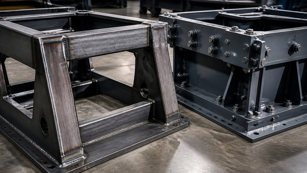
A welded frame usually provides greater joint rigidity, while a bolted frame is easier to ship, assemble, and modify. A welded joint fuses steel parts into a continuous connection; a bolted joint clamps parts together with bolts and mating surfaces. The better choice depends on machine loads, required alignment, transport limits, and whether the base may need changes later.
Welding can distort a frame as heat expands and contracts the steel. The fabrication drawing should identify the steel grade, plate and tube sizes, weld locations, and required machined surfaces. It should also state how the frame will be checked for flatness and alignment after welding. These details help the buyer confirm that the base suits the machine, rather than relying on a general claim of rigidity.
Bolted frames can be disassembled for transport or reconfigured, but joint design matters. Specify bolt grade, size, hole locations, and any locking method, then define how fasteners will be inspected or retightened. Vibration, repeated loading, and access for maintenance affect those requirements. For either design, include lifting points and the machine’s mounting interface in the drawing so they can be reviewed before fabrication.
How Welded and Bolted Machine Frames Compare
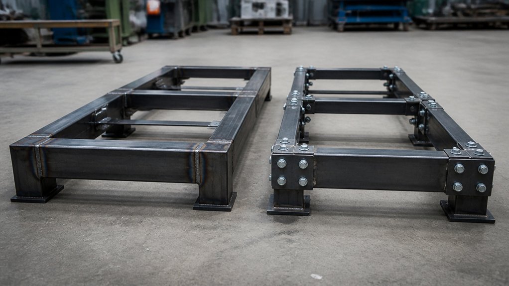
Welded frames suit permanent assemblies with fewer separate parts, while bolted frames suit equipment that may need repair, replacement, or reconfiguration. In a welded steel frame, a fabricator joins members with processes such as gas metal arc welding (GMAW), then machines mounting surfaces if the design requires precise alignment. Welding heat can distort parts, so the drawing should identify weld locations, access for the welding torch, and surfaces that need machining.
Welded joints can develop fatigue cracks under repeated loading. Fatigue is damage that builds up as a part experiences repeated stress; joint shape, weld quality, loads, and service conditions affect the risk. Specify inspection requirements and any applicable welding code on the drawing or purchase specification.
A bolted frame connects members with plates, brackets, and threaded fasteners. The specification should identify fastener material and grade, along with the required tightening method and any locking feature. Preload means the tension created in a bolt when it’s tightened; the required preload depends on the joint design and fastener specification. Bolted joints can loosen under vibration, and clearance between fasteners and holes can allow movement. Compare the options based on expected loads, maintenance access, required alignment, and whether parts must be replaced or rearranged.
Compare Frame Stiffness, Vibration, and Load Capacity
Frame stiffness, vibration, and load capacity depend on the members, connections, material, and supports—not simply on whether the frame is welded or bolted. A welded joint fuses steel parts, while a bolted joint clamps them together; either can be stiff if designed for the loads and operating conditions.
For example, a frame made from ASTM A36 steel tube needs suitable tube dimensions, wall thickness, and support points to limit bending. Weld size and quality affect how forces pass through a welded joint. In a bolted joint, fastener size and grade, bolt spacing, plate thickness, and clamping force affect stiffness; joint slip means movement between connected parts. The required details depend on load direction, repeated loading, and access for inspection.
Vibration performance depends on operating speed, frame mass, and damping, which is the reduction of vibration energy. A rigid welded frame may transmit vibration rather than absorb it. Bolted joints can also move or loosen under repeated vibration, so the design may need locking features and routine checks. An engineer should assess resonance, when operating vibration matches a frame’s natural vibration frequency, and resulting deflection.
Check load capacity by evaluating member strength, connection strength, and the path loads take through the frame. Weld capacity depends on weld dimensions, workmanship, and base-metal strength; bolted capacity depends on fastener strength, plate bearing, and resistance to slip.
Plan for Frame Installation, Maintenance, and Changes
Plan installation and maintenance before selecting a welded or bolted machine base, because each design affects transport, access, and future repairs. Check the route to the installation site, lifting points, floor anchors, and clearance around the equipment. A welded base arrives as one assembly and may need more lifting capacity and transport space. A bolted base can ship in sections and be assembled near its final position, but assembly requires suitable tools and time to align the parts.
For a welded base, plan how technicians will inspect joints and repair damage. A welded joint joins metal parts by heat; repairing it may require cutting, rewelding, and refinishing the affected area. For a bolted base, specify access to fasteners and a method for checking their tightness. Bolted connections allow sections to be removed, but maintenance must include checking fasteners and joint condition.
Tell the fabricator the equipment’s installation route, lifting method, anchor locations, and service-access needs. The better choice depends on whether transport and assembly constraints or disassembly and repair needs matter more over the equipment’s service life.
Choose a Machine Frame by Load and Setup
Choose a welded steel frame for a machine with high or changing loads when a continuous structure helps control deflection; choose a bolted steel frame when transport, assembly, or future changes make separate sections more practical. Deflection is the amount a frame bends under load. The right choice depends on machine weight, payload, vibration, impact, attached equipment, and the limits for alignment and movement.
For a welded frame, specify the steel grade, section sizes, weld locations, and inspection requirements on the drawing. The fabricator should account for weld distortion, which is heat-related movement that can affect flatness and alignment. Check that the finished frame can pass through shipping routes and site entrances, and that lifting points suit its weight and shape.
For a bolted frame, specify the bolt grade, joint layout, and how fasteners must be tightened. Joint design must resist slipping or loosening under vibration. Ask for calculations or other design evidence where loads are significant. For either option, confirm floor capacity, anchoring, leveling provisions, and access for installation and maintenance. The brief should state allowable deflection and alignment requirements, plus who’s responsible for verifying them.
Frequently Asked Questions
What Materials Are Commonly Used to Fabricate Machine Base Frames?
Machine base frames are commonly fabricated from welded carbon steel, cast iron, stainless steel, or aluminum. The right choice depends on load, stiffness, corrosion exposure, mass, and how the frame will be made and installed.
Welded carbon steel, such as ASTM A36 plate and shapes, suits many frames because it is widely available and can be cut and welded. Welding can distort the frame, so the drawing should specify machining datums—the reference surfaces used to locate parts—and checks for flatness and alignment after welding. Stress relief may be needed when distortion or residual stress could affect precision.
Cast iron is often chosen for heavy machine bases that need vibration damping, meaning the material reduces transmitted vibration. It is usually cast to shape, so the design must allow for foundry limits and machining of mounting surfaces. Stainless steel, such as Type 304, is useful where moisture or cleaning chemicals create corrosion risk; aluminum can reduce frame mass but may require larger sections to meet stiffness needs.
For a purchase specification, state the material grade, section sizes, weld requirements, machined surfaces, and inspection method. Cost depends on material, fabrication and machining time, finishing, and any stress relief or corrosion protection.
How Are Welded Machine Frames Protected Against Corrosion?
Protect welded machine frames by removing mill scale, rust, oil, and weld residue, then applying a coating suited to the steel and service environment. Mill scale is the dark oxide layer formed during hot rolling; coatings may not adhere reliably if it remains on the surface.
Specify surface preparation and coating as separate requirements. Abrasive blasting removes scale and rust, while solvent cleaning removes oil and grease. State whether weld spatter, sharp edges, and crevices must be cleaned or smoothed, since they can leave thin spots or trap moisture.
Choose the coating based on exposure, frame geometry, and maintenance needs. Epoxy primer and polyurethane topcoat can protect painted frames; powder coating applies and cures a dry polymer finish. Hot-dip galvanizing coats steel with zinc, but the frame must be designed with vent and drain openings so molten zinc can reach internal spaces and escape. Sealed finishes can limit water entry at joints, but they do not replace surface preparation.
Before production, identify the steel grade, coating system, required surface preparation, and areas that must remain uncoated for machining or electrical grounding. Ask for coating product data sheets and inspection records, including checks for coating thickness and coverage. The appropriate system depends on chemical exposure, outdoor weather, abrasion, and the consequences of coating damage.
Can Welded and Bolted Frames Support Precision Leveling Feet?
Welded and bolted frames can support precision leveling feet if their mounting points and structure are designed for the loads. A leveling foot is an adjustable threaded support used to set equipment height and compensate for an uneven floor. The required capacity and adjustment range depend on the equipment’s weight, load distribution, vibration, and floor conditions.
For a welded steel frame, specify mounting plates made from the same or compatible steel as the frame, with enough thickness and area to spread each foot’s load into the surrounding members. The fabricator should detail the weld size and length for the applied load, rather than relying on a plate welded only around its edge. For a bolted frame, use steel plates with threaded inserts or nuts secured against rotation; the bolt pattern and joint design must resist loosening and frame movement.
Frame stiffness matters in both designs. Deflection—the frame’s bending under load—can shift equipment out of level even when the feet are correctly adjusted. In the drawing or purchase specification, identify each foot location, its rated load, the mounting detail, and the required level or alignment tolerance. Have the engineer verify the frame and connections for the actual operating loads.
What Documentation Should Accompany a Custom Machine Base Frame?
For a custom machine base frame, require approved fabrication drawings, material records, weld documentation, inspection results, and finish requirements. These records let the buyer compare the delivered frame with the design and identify the materials and processes used.
The drawing package should show dimensions, hole locations, interfaces, weld symbols, and any machining or flatness requirements. A weld procedure specification (WPS) describes how a weld is to be made; require one when the contract, governing code, or risk level calls for it. Material test reports identify the supplied steel grade and heat number, which links the material to its production batch.
Inspection records should cover the checks specified in the purchase documents. These may include dimensional inspection, visual weld inspection, and non-destructive testing, which checks for flaws without cutting the part. State the inspection method and acceptance criteria in advance, based on the applicable code and the frame’s service conditions.
Also specify the coating or finish, surface preparation, and any required coating inspection. Traceability records connect materials, welds, and inspection results to the frame. The required documents depend on the frame’s loads, operating environment, governing standards, and the consequences of failure.
How Can Frame Dimensions Be Verified Before Fabrication?
Verify frame dimensions before fabrication by comparing the approved drawing with the 3D model, then checking critical dimensions against the specified part or assembly. The drawing should identify the material, such as ASTM A36 carbon steel, and the required thickness; the model and drawing must agree on the frame’s overall size, hole locations, and connection points.
Check dimensions that affect fit or assembly independently, using the measurement method suited to the feature. For example, verify hole spacing from the drawing’s stated datum, a reference surface used to locate measurements, rather than measuring from an edge that may vary. Confirm that the specified fabrication tolerances—the permitted variation from a stated dimension—fit the joining method and the parts that connect to the frame. The required tolerances depend on the design, material thickness, cutting and welding processes, and assembly conditions.
Record any mismatch between the drawing, model, and supplied specifications before releasing the job. Resolve the discrepancy with the design authority, and issue a revised, approved drawing or model so production uses one controlled set of dimensions.