
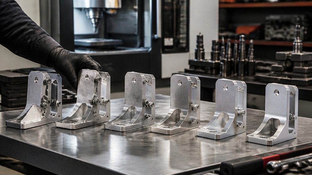
Five design changes can reduce fabrication cost: remove unused features, choose readily available materials, limit tight tolerances to critical interfaces, standardize parts, and improve sheet nesting. For example, removing an unnecessary mounting tab from a laser-cut bracket can eliminate a cut and simplify assembly.
Choose material based on the part’s strength, corrosion resistance, forming needs, and operating environment. For sheet-metal parts, specifying a commonly stocked grade of mild steel or 304 stainless steel may avoid sourcing delays or extra handling; the best choice depends on the application. A tolerance is the permitted variation in a part’s dimensions. Tight tolerances can require slower machining, extra inspection, or more scrap, so apply them only where fit or function depends on them.
Standardizing hole sizes, bends, fasteners, and part designs can reduce setup changes and simplify purchasing. Sheet nesting—the arrangement of flat patterns on a sheet before cutting—can reduce unused material and handling, but the result depends on part geometry, material, and cutting process. Check the drawing for features that add operations without serving a clear function, and confirm that material, tolerances, and shared dimensions suit the part’s intended use.
Apply DFM to Simplify Part Geometry
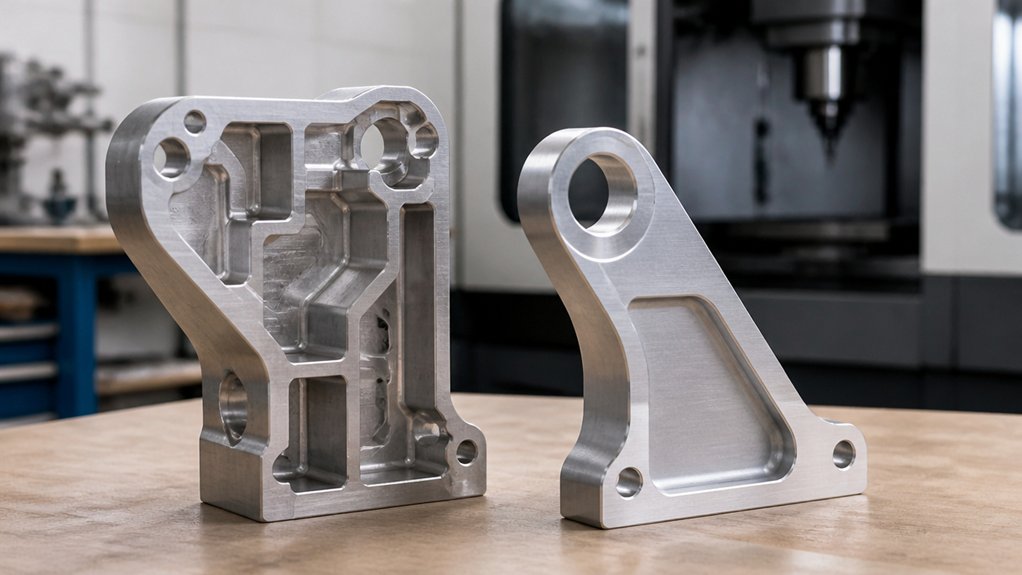
Remove features that don’t support fit, strength, or operation, because simpler geometry can reduce machining time, setups, and inspection work. For a CNC-milled aluminum plate, for example, check whether deep pockets or decorative contours can be removed without affecting mounting, clearance, or load-bearing needs. A pocket’s effect depends on the part’s loads, material grade, and wall thickness.
Set tolerances—the permitted variation in a dimension—only as tightly as the interface or function requires. The appropriate limits depend on how the part mates with other components and on the selected process, such as laser cutting, press-brake forming, or CNC machining. Tighter tolerances can require slower processing and more measurement.
Use standard hole sizes, fasteners, and bend radii where the design allows. For sheet metal, specify the alloy and thickness, then arrange flat profiles to improve nesting, the layout of parts on a sheet, and reduce offcuts. Bend results depend on the material, thickness, tooling, and bend direction, so confirm the design with the fabricator before release. Update drawings and models after approved changes, including dimensions, material specifications, and interface details.
Choose Materials That Machine Easily
Choose a machinable metal grade only after confirming that it meets the part’s strength, wear, and environmental requirements. For CNC milling or turning, compare specific candidates such as 6061-T6 aluminum, 303 stainless steel, and 1018 carbon steel; their cutting behavior and suitability differ by operation and service conditions.
Machinability describes how readily a material can be cut while controlling tool wear, chips, and surface finish. Free-machining grades, such as 303 stainless steel, may cut more easily than other grades in the same alloy family, but their corrosion resistance or forming performance may not suit every part. Ask the engineer or buyer to check the applicable material specification and confirm that the selected grade meets the design requirements.
Check that the grade is available in the required form and dimensions, such as bar, plate, or tube. Stock size can affect lead time, material waste, and the amount of machining required. Include any heat treatment or finishing in the review, since these steps can change material properties and affect the machining sequence. Before approving the drawing or purchase order, specify the exact grade, product form, and source, and confirm that the planned cutters, coolant, and workholding suit the operation.
Set Practical Tolerances and Standardize Parts
Use the loosest tolerances that still meet the part’s function and assembly requirements. A tolerance is the permitted variation from a dimension on a drawing. Tight tolerances can increase machining time, inspection work, and the risk of rejected parts, so apply them only where variation could affect fit, alignment, sealing, movement, or safety.
For a machined steel shaft, for example, the required fit with its mating bore determines how closely the shaft diameter must be controlled. For a sheet-metal bracket cut by laser and bent on a press brake, hole locations and bend positions may need closer control if they determine how the bracket mounts. The right limits depend on the process, material, part geometry, and assembly; confirm that the selected fabricator can meet them consistently.
Standardize parts and specifications across assemblies where the design allows. Reuse common fasteners, hole sizes, stock thicknesses, and commercially available components to simplify purchasing, setup, tooling, and inspection. Record approved sizes and tolerance classes in drawing standards, and check new designs against those rules before release. This can reduce variation and revision errors without compromising function.
Reduce Sheet-Material Waste With Better Nesting
Efficient nesting reduces sheet-metal scrap by placing compatible parts together while preserving the clearances and orientations required by the cutting process. Nest parts made from the same alloy, material grade, thickness, and finish; for example, 304 stainless steel and 5052 aluminum shouldn’t share a sheet plan. The right grouping also depends on order quantities and whether parts can be produced and delivered together.
For laser cutting, kerf is the width of material removed by the beam. The nesting plan must account for kerf and the machine’s cutting and part-removal requirements; the needed spacing depends on the equipment, material, and part shape. Rotating a profile can improve sheet use, but only when it doesn’t conflict with grain direction, bend orientation, or visible-surface requirements. Confirm those constraints in the part drawing and forming instructions.
Check the proposed layout against the sheet size, machine limits, and required quantities. Combining jobs may use leftover areas, but can add handling or delay a job that’s ready to run. Ask for expected material yield by part family and review it alongside scrap and production constraints. Consistent part geometry can also help nesting software find workable arrangements, especially when repeated components have similar shapes.
Frequently Asked Questions
How Can Early Supplier Collaboration Reduce Fabrication Costs?
Early supplier collaboration can reduce fabrication costs by finding design changes before tooling, programming, or material is committed. A manufacturability review checks whether a part’s shape and tolerances suit its production process.
For a laser-cut and press-brake-formed part in 5052-H32 aluminum sheet, a fabricator can review bend locations, hole spacing, and material use. Press-brake forming bends sheet metal with a punch and die. Moving a hole away from a bend, combining separate parts, or adjusting a profile may simplify cutting and forming. Whether a change is suitable depends on the part’s function, load, finish, and assembly requirements.
Ask the supplier to identify the proposed process, material grade and thickness, critical dimensions, and any features that may require extra setups or secondary operations. A setup is the preparation needed to run a job, such as changing tooling or repositioning a part. Compare proposed changes against the drawing and application requirements, and request revised drawings before approving production. Savings depend on order volume, material yield, equipment, and the cost of any added inspection or finishing; they are not guaranteed.
When Should a Design Undergo a Manufacturability Review?
Schedule a design for manufacturability review before approving the design for production, after the main concept is defined but before detailed drawings are released. A design for manufacturability review checks whether the part can be made with the specified process, material and production volume.
Review the design while changes to shape and construction are still practical. For a laser-cut and press-brake-formed steel part, check whether the bend locations, hole positions and material thickness suit the planned process. For a welded assembly, review joint access, weld sequence and whether the specified steel grade is suitable for the forming and welding steps. The right choices depend on the part’s function, required finish, available equipment and order quantity.
Include the buyer, design engineer and intended fabricator in the review, and provide the latest drawings, material and finish requirements, production quantity and inspection criteria. Ask the reviewer to identify features that may need extra setups, special tooling or additional inspection. Resolve those points before releasing drawings for production; late changes can require revised tooling, replacement material or rework.
How Do Production Volumes Affect Fabrication Cost?
Higher production volumes usually lower the fabrication cost per part because setup and programming costs are spread across more units. The size of the reduction depends on the process, material, part geometry, and how often the design changes.
For laser cutting, for example, the fabricator must prepare the cutting program and set up the sheet and machine. Those tasks take time whether the order is small or large. A larger batch spreads that work across more parts, but material use, cutting time, and handling still add cost to each unit.
Standardizing parts can improve the savings. Parts that share material, thickness, and cutting requirements may fit into the same production run, reducing setup changes and scrap. For sheet metal, specify the alloy and thickness, such as 0.125-inch (3.175 mm) 5052 aluminum, rather than relying on a general description like “aluminum sheet.”
Before setting a volume, confirm the design, tolerances, finish, and inspection requirements. A manufacturability review checks whether the design suits the chosen process and can reveal changes that reduce handling or rework. The best order quantity depends on storage, demand, design stability, and the cost of holding unused parts.
Can Prototyping Help Identify Costly Manufacturing Issues?
Yes. A prototype can reveal costly manufacturing problems before production tooling is ordered or full-scale fabrication begins.
For a sheet-metal part made by laser cutting and press-brake forming, a prototype can show whether bends, holes, and mating parts fit as intended. It can also expose assembly problems, such as a fastener that is hard to reach or a flange that clashes with another component. These checks help identify design changes before they affect a larger production run.
A prototype can also compare material and process choices. For example, a part designed for 0.060-inch (1.52 mm) 5052-H32 aluminum may need different bend details from one made in 0.060-inch (1.52 mm) 304 stainless steel. The suitable choice depends on strength, corrosion exposure, appearance, forming requirements, and how the part will be joined.
When reviewing a prototype, check dimensions, fit, edge condition, bend locations, and assembly sequence against the drawing. Record any changes clearly. The cost impact depends on factors such as material use, setup changes, extra operations, scrap risk, and whether production tooling must be revised.
How Should Manufacturers Evaluate Automation Investments?
Evaluate an automation investment by comparing its expected effect on production cost, output, quality, and reliability with the current process. Establish a baseline using records for the specific part and operation, such as laser cutting 0.125-inch (3.18 mm) 304 stainless steel or robotic welding of a mild-steel frame.
Track cycle time, the time to complete one operation; throughput, the number of acceptable parts produced over a period; labor hours; scrap and rework; and downtime. Include setup, programming, tooling, maintenance, and operator training in the estimate. These factors can change the result, especially when production volume or part mix varies.
Use a return-on-investment model to compare scenarios. Return on investment measures expected financial gain against the investment cost; payback time estimates how long savings take to recover that cost. Test assumptions for realistic production schedules, changeovers, and equipment availability rather than relying only on the machine’s rated speed. The right choice depends on part geometry, material, tolerances, batch size, and how consistently the process runs. Check that automation does not reduce inspection access or make defects harder to detect.