
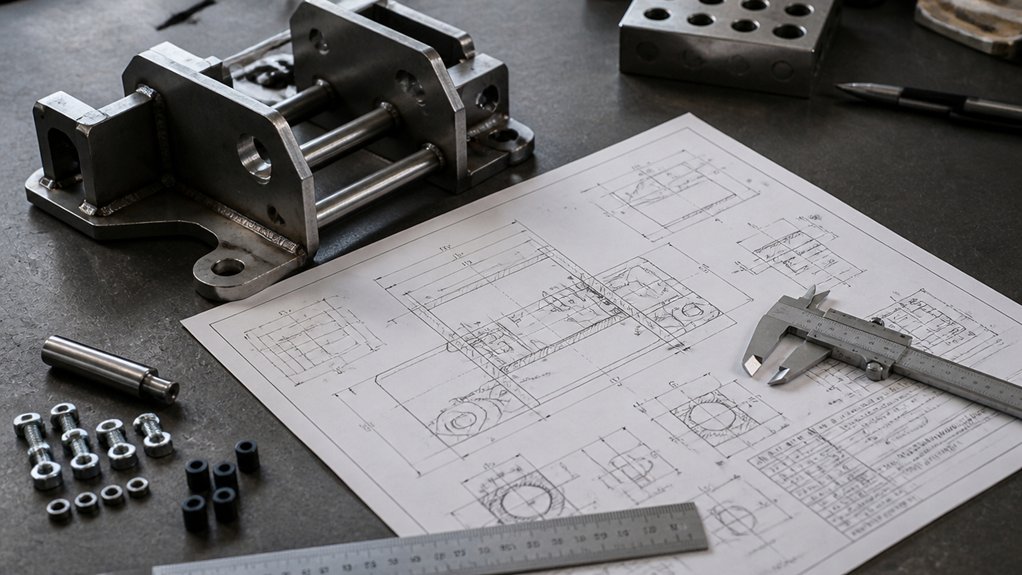
A fabrication drawing should identify the part and show the information needed to make and inspect it: material and grade, stock thickness, manufacturing processes, views, dimensions, tolerances, datums, welds, finishes, hardware, and coatings. A datum is a reference point, line, or surface used to locate and measure features.
Include the part number, drawing revision, approval status, and units so production and purchasing can distinguish the current, authorized drawing from earlier versions. Name the material and grade—for example, 304 stainless steel—and specify thickness. The required material depends on the part’s load, environment, forming process, and applicable standards.
Use views and dimensions to define features that matter, including hole locations, bends, and cutouts. State tolerances, or permitted variation, where they affect fit or function; the appropriate limits depend on the process and assembly. Identify the datum scheme so inspection uses the same references as production.
Specify processes such as laser cutting, press-brake forming, and welding when they affect the result. Show weld locations and required details, plus finish, hardware, and coating requirements. These choices can affect material selection, inspection, lead time, and cost. Avoid relying on notes such as “deburr” or “paint” when the required condition, coating type, or coverage needs to be controlled.
What Must a Fabrication Drawing Show?
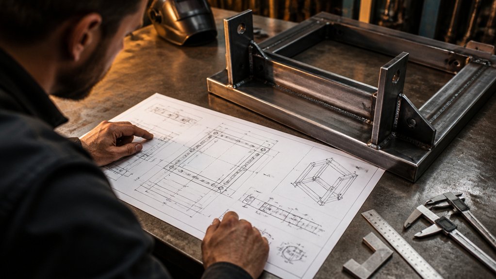
A fabrication drawing must show the information needed to make and inspect the part without guesswork. Identify the part, drawing revision, units, and approval status so the buyer and production staff can confirm they’re using the current document.
Specify the material by grade and product form, such as ASTM A36 plate or 304 stainless-steel sheet, and state its thickness. Name the required process when it affects the result, such as laser cutting, press-brake forming, or MIG welding; MIG means metal inert gas welding. Choose material and process based on the part’s loads, environment, finish, and the supplier’s equipment.
Dimension the part, including hole locations, bend details, and features needed for assembly. State tolerances—the permitted variation from a dimension—where they affect fit or function, and identify how critical features should be inspected. Avoid adding unsupported precision: required tolerances depend on the process, material, and design.
Add notes for weld locations and requirements, fasteners, edge conditions, coatings, and other treatments. Include a title block, drawing scale, and any applicable standards. Keep notes legible and consistent, and check them against the design and purchasing specification before release. Unclear dimensions, tight tolerances, special finishes, and extra inspection requirements can affect production time and cost.
Which Views and Dimensions Define the Part?
The part is defined by dimensioned front, top, and side views, with section or detail views added when they clarify features the shop must make or inspect. A section view shows the part as if cut through; a detail view enlarges a small area. An isometric view shows three-dimensional form, but it doesn’t replace orthographic views, which show the part from separate directions and carry its manufacturing dimensions.
For a laser-cut steel plate, show the plate outline, thickness, hole and slot locations, and any cutouts. For a press-brake bend, add a section or side view that makes the bend direction and finished shape clear. State the material grade and thickness on the drawing; the suitable grade and thickness depend on the part’s load, environment, forming process, and applicable specification.
Dimension overall length, width, and height in inches, with millimetres in brackets. Locate holes, bends, and cutouts from clear reference edges or datums—the points or surfaces used to establish measurements. Avoid duplicate dimensions and long chains that can accumulate error. Use the applicable drawing standard for units, symbols, and dimension placement, and identify any required tolerances, the allowed variation from a stated dimension. Keep dimensions legible and outside the part outline where practical.
How Do Materials and Tolerances Guide Fabrication?
Material and tolerance notes guide fabrication by identifying the stock to buy and the dimensions to make and inspect. Name the alloy or steel grade, thickness, and governing material standard, such as an ASTM specification, so purchasing and production refer to the same material. For sheet-metal bending, note grain direction or material condition when it affects cracking, springback, or strength.
Set tolerances—the permitted variation from a stated dimension—according to how the part functions and how it will be made. A laser-cut edge, a press-brake bend, and a machined hole have different process capabilities, so avoid applying one tight tolerance to every feature. Tight limits may be needed for mating parts, moving clearances, or inspection requirements; noncritical dimensions can use a stated general tolerance.
Use datums, which are reference surfaces or features for locating and measuring the part, when inspection or assembly depends on a consistent setup. Add geometric controls, such as a position tolerance for a hole pattern, only when they clarify the required relationship between features. Identify whether dimensions apply before or after forming or machining when those operations can change the finished size. Keep welding, coating, assembly, and revision requirements in separate drawing notes.
What Weld, Finish, Assembly, and Revision Details Matter?
Specify the welds, finish, assembly details, and drawing revision on the released drawing and its notes. A weld symbol is a drawing mark that tells the fabricator the joint type, weld size, length, location, and which side to weld. Name the applicable welding standard, such as AWS D1.1 for structural steel, when it fits the material and application; state inspection criteria, welder qualification requirements, and any nondestructive testing, such as ultrasonic testing, which uses sound waves to find internal flaws. Requirements depend on the part’s material, service conditions, and governing code.
Describe surface preparation and the coating system, including coating type, specified thickness, color, and areas to mask. Identify the coating manufacturer’s product data or applicable specification so the finish can be checked against a defined requirement. State hardware and fastener materials or grades, and show the assembly sequence when it affects fit, access, or function. Mark critical interfaces—surfaces or features that connect to other parts—and say whether components ship loose or assembled.
Put the revision identifier, release date, and a concise description of each change in the title block or revision table. Check that dimensions, weld symbols, notes, and views agree with the current revision. Clear requirements reduce interpretation differences; added inspection, coating steps, and assembly work can also affect lead time and cost.
Frequently Asked Questions
Who Is Responsible for Approving a Fabrication Drawing?
The designated engineer or authorized design owner should approve a fabrication drawing before production begins. That person is responsible for confirming that the drawing meets the design requirements and is suitable for the intended use.
The approver depends on the project. For a customer-owned design, approval may come from the customer’s engineer or another person with written authority to release drawings. For a regulated product or a project with a licensed engineer, the required approval may be set by contract, code, or the project’s quality plan. A buyer can coordinate the review, but should not approve technical changes unless authorized to do so.
The review should cover material, grade, thickness, dimensions, tolerances, weld details, finishes, and any notes that affect fabrication or inspection. A tolerance is the permitted variation from a stated dimension. If the drawing changes after approval, the design owner should review and approve the revision before the affected work proceeds.
Keep a dated record of the approved drawing and its revision identifier. This helps production and inspection teams work from the same document and reduces the risk of rework caused by outdated or unauthorized details.
What Software Is Commonly Used to Create Fabrication Drawings?
AutoCAD, Revit, Tekla Structures, and SolidWorks are commonly used to create fabrication drawings. The right choice depends on the product, material, manufacturing process, and the files the fabricator must exchange with the buyer or other project teams.
AutoCAD is a computer-aided design (CAD) program used for 2D drawings, such as dimensioned plate layouts and sheet-metal profiles. Revit is building information modeling (BIM) software, which links 3D building elements to project data; it is useful when metalwork must coordinate with architectural and structural models. Tekla Structures focuses on detailed 3D models of steel structures and connections, while SolidWorks is often used for 3D mechanical parts, assemblies, and sheet-metal components.
Before choosing software, confirm that the drawing can show the information needed to make and inspect the part: material and grade, thickness, dimensions, hole locations, weld symbols, surface finish, and revision status. Ask which file formats the fabricator can use and whether the files must support nesting, CNC cutting, bending, or model-based coordination. A neutral exchange format may preserve geometry, but not every note or manufacturing detail, so agree on a drawing PDF and a usable model or CAD file where needed.
How Should Fabrication Drawings Be Shared With Suppliers?
Send the supplier a controlled PDF drawing and, when needed, the native CAD file—the editable file used to create the drawing—through a secure, version-managed portal. The PDF gives production staff a stable document to review and print; the CAD file can help with programming cutting or forming equipment. Agree on the file formats with the supplier, since software compatibility and the manufacturing process affect what they can use.
Put a revision identifier, issue date, and approval status on every drawing. A revision is a recorded change to the design. Keep older revisions available for reference, but clearly mark them as superseded so they are not used for production. Include a change log that describes what changed, such as a hole location, material grade, or bend detail.
Set access controls so only authorized people can view or change files. Ask the supplier to acknowledge the current revision before work starts, and agree on a deadline for questions or proposed changes. Resolve discrepancies in writing and issue a revised, approved drawing rather than relying on verbal instructions. For parts made from sheet steel, for example, specify the grade and thickness, along with dimensions, tolerances, and any required surface finish; the details depend on the part and process.
When Should a Fabrication Drawing Be Updated After Release?
Update a released fabrication drawing when an approved change affects the part’s design, material, tolerances, or manufacturing process. A tolerance is the permitted variation in a dimension; changing it can affect fit, function, inspection, and production cost.
First assess the change against the part’s intended use and related documents, such as assembly drawings, bills of materials, and inspection plans. For example, replacing mild steel with 304 stainless steel, changing a laser-cut feature, or revising a weld detail may require updates to material specifications, forming or welding instructions, and inspection criteria. Whether a change needs a new drawing revision depends on its effect on safety, function, fit, compliance, and downstream work.
Follow the organization’s change-control process before production uses the revision. Record the reason, obtain approval from the responsible design or engineering authority, update the drawing and affected documents, and identify the revision clearly. Then distribute the controlled update to every affected supplier and production or inspection team, and confirm that obsolete copies are withdrawn. If work is already underway, assess whether parts made to the previous revision can be accepted, reworked, or must be replaced before authorizing the change.
How Can Teams Prevent Unauthorized Changes to Fabrication Drawings?
Prevent unauthorized changes to fabrication drawings by limiting edit access, controlling revisions, and requiring documented approval before a change reaches production. A revision is a recorded update to a drawing; it should identify what changed, who approved it, and when it took effect.
Store drawings in a version-controlled repository, a system that preserves prior revisions and records changes. Give edit rights only to people responsible for engineering or drawing control, and use read-only copies for production and purchasing. Mark approved files as released, meaning authorized for use, and prevent users from overwriting them.
Route proposed changes through a change-control process. Require the responsible engineer and, where relevant, the buyer or customer to approve changes that affect material grade, thickness, dimensions, weld details, finish, or inspection requirements. The approval record should state whether existing parts, stock, or purchase orders are affected.
Keep an audit trail, a record of who accessed or changed a file and when. Train staff to compare the drawing revision on the work order with the released file before cutting or forming material. If a discrepancy appears, pause the affected work and report it to the drawing owner rather than making an informal correction.