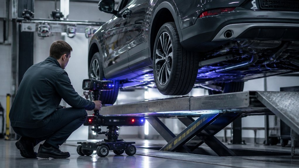
AI and machine vision can help inspect fabricated metal parts by comparing images and sensor readings with a digital drawing, but they do not replace a qualified inspector. Machine vision uses cameras and image-processing software to identify visible features such as bends, holes, and weld irregularities.
For a useful inspection, the drawing must specify the material, grade, thickness, dimensions, and acceptance criteria. For example, a drawing for a mild-steel plate bracket should identify the steel grade and plate thickness, then state the required hole locations and weld details. The inspection system can compare measurable features with those requirements, but its results depend on camera setup, lighting, calibration, and access to the part.
AI systems may flag surface marks or changes in shape, but they can miss defects that are hidden inside a weld or obscured by scale, paint, or poor lighting. A qualified inspector should review flagged results and decide whether additional checks, such as ultrasonic testing, are needed. Ultrasonic testing uses sound waves to find internal flaws. The right inspection plan depends on the part’s function, material, fabrication process, drawing requirements, and the consequences of failure.
How Do AI and Machine Vision Support MOT Checks?
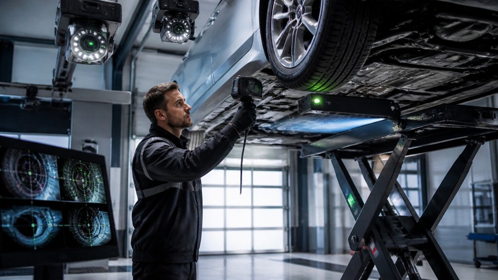
AI and machine vision support metal fabrication by turning drawing files, camera images, and equipment readings into reviewable production and inspection records.
Machine vision means software that analyzes images to identify features or measure dimensions. It can compare a laser-cut or machined part with a digital drawing, flag visible defects in a weld, or check whether holes and edges are in the specified locations.
Results depend on the material, surface finish, lighting, camera setup, and inspection method. Reflective stainless steel, for example, can create glare that hides a surface defect. A camera system may also miss internal weld flaws that require another inspection method, such as ultrasonic testing, which uses sound waves to examine material below the surface. The drawing should identify the features and acceptance criteria that matter; the appropriate checks depend on the part’s function and applicable requirements.
Sensor readings from laser cutters, press brakes, or welding equipment can be linked to job records to reduce manual data entry and trace each production step. Automated alerts are prompts for review, not proof that a part meets specification. Confirm results using suitable measuring tools and inspection procedures, and account for calibration drift, poor image quality, and differences between equipment. Protect design files and production data, and check that the system evaluates parts consistently across material finishes and production conditions.
Which MOT Defects Can AI Detect?
AI can detect visible defects in fabricated metal parts, including cracks, incomplete welds, surface corrosion, distortion, and missing or misplaced features. Detection depends on the camera setup, lighting, surface finish, and defect size.
AI can flag visible cracks, incomplete welds, corrosion, distortion, and misplaced features, depending on imaging conditions and defect size.
For sheet-metal parts made from carbon steel, stainless steel, or aluminum, machine-vision software can compare images with a drawing or approved reference part. It can flag holes, slots, bends, and edges that appear out of position. A drawing’s dimensions and tolerances define whether a variation is acceptable; the software shouldn’t treat every visual difference as a defect.
Weld inspection has limits. Cameras may reveal visible cracks, undercut, or inconsistent weld appearance, but they can’t reliably identify internal porosity or lack of fusion. Those defects may require another method, such as ultrasonic testing, which uses sound waves to examine material below the surface. The suitable method depends on the joint, material thickness, access, and inspection requirements.
A useful inspection brief identifies the part material and grade, drawing revision, critical features, and defects to flag. It should also specify how findings are recorded, such as annotated images linked to part numbers. This makes automated checks easier to review alongside dimensional inspection and any required nondestructive testing.
What Can AI Miss in an MOT Inspection?
Automated inspection can miss metal defects that its camera, sensor, or training data can’t reliably identify. For fabricated parts, this may include a crack beneath paint, corrosion hidden inside a folded seam, or distortion that appears only after welding or assembly. The risk depends on the material, joint design, surface finish, and inspection method.
A camera may not reveal defects inside a weld or beneath a coating. Those require a suitable method, such as ultrasonic testing, which uses sound waves to find internal flaws, or magnetic-particle testing, which reveals surface and near-surface flaws in ferromagnetic metals such as carbon steel. The inspection plan should match the part’s drawing, material specification, and acceptance criteria.
Image-based checks can also be affected by glare, dirt, shadows, and blocked views. Poor camera calibration can distort dimensions, while low image resolution can hide small cracks or uneven edges. For a laser-cut 304 stainless-steel bracket, for example, verify hole locations and edge condition against the drawing; the required inspection method and tolerance depend on the part’s function and specified standard.
Before production, state which features need inspection, how they’ll be measured, and what records the supplier must provide. Include checks after processes that can change the part, such as welding, forming, or coating.
How Do Inspectors Verify AI Findings?
Inspectors verify AI findings by comparing each alert with the part drawing, material specification, and applicable acceptance criteria. An alert is a prompt to check the work, not proof that a defect exists.
For a laser-cut carbon-steel plate, an inspector may examine the cut edge for dross, which is metal residue left by the cutting process, and compare hole locations with the drawing. For a welded joint, the inspector checks the specified weld size and profile; visual inspection can identify surface issues but can’t confirm hidden flaws inside the joint. Those may require a suitable nondestructive test, such as ultrasonic testing, which uses sound waves to detect internal discontinuities.
The check depends on the process, material, and part function. A stainless-steel surface may need different lighting and cleaning than a painted mild-steel part, while a tight-fit assembly may require measurement of hole position or flatness. Inspectors should use calibrated measuring tools and the drawing’s stated tolerances rather than assume a universal limit.
If an image is unclear, the inspector can clean the surface, adjust the viewing angle, or repeat the measurement. The record should identify the feature checked, the method used, the measured result, and any remaining uncertainty.
How Does AI Change MOT Checks for Garages and Drivers?
AI changes a metal fabrication inspection by using machine vision—software that analyzes camera images—to flag visible defects for a person to review. For example, image systems can identify surface marks, incomplete welds or inconsistent cut edges on steel parts. Their usefulness depends on the material, finish, lighting, camera setup and defect criteria.
For a clear brief, specify the material and grade, such as 304 stainless steel or ASTM A36 carbon steel, along with the part’s dimensions, finish and fabrication process. State which features need inspection, such as weld seams, drilled holes or bent flanges, and provide drawings that identify critical dimensions and acceptable defects. A tolerance, or permitted variation from a specified dimension, should come from the part’s design requirements or an applicable drawing standard.
AI can make image capture more consistent and direct attention to areas that may need closer inspection. It can’t establish whether a part meets requirements unless the inspection criteria are defined and validated for that job. A qualified inspector must verify flagged findings and use suitable measurement methods, such as calipers for dimensions or weld inspection procedures for joints. The appropriate checks depend on the part’s function, material, process and required documentation.