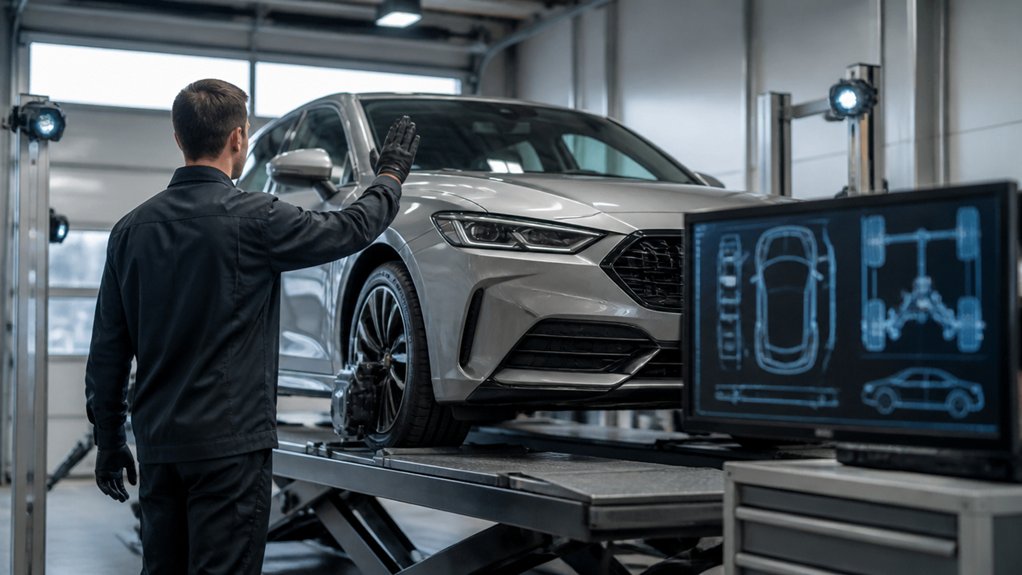
In the coming years, MOT vehicle inspection stations will embrace AI more and more. AI can help a metal fabrication buyer compare inspection records, but it cannot replace a clear drawing or a qualified inspector’s judgment. For a part made from 304 stainless steel sheet, for example, image-based tools may flag visible scratches, burrs (sharp edges left after cutting), or differences from an approved reference image.
The result depends on the process and the defect. A camera may capture surface marks on a laser-cut panel, but it cannot reliably confirm an internal weld flaw or measure a hole’s diameter from an image alone. Those checks may require methods such as ultrasonic testing, which uses sound waves to find internal flaws, or a calibrated measuring tool.
A useful inspection brief identifies the material grade, thickness, drawing revision, critical dimensions, and acceptable surface condition. It should also state how each feature will be checked. A tolerance—the allowed difference from a specified dimension—should come from the part’s function, drawing requirements, or an applicable published standard, not from an AI system’s image match.
Inspection records can help buyers compare parts across production runs and document nonconformances, meaning departures from the drawing or specification. Their value depends on consistent lighting, camera position, measurement methods, and traceable links to the part and drawing revision.
What AI Vehicle Inspection Does in an MOT
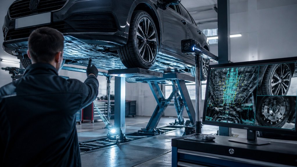
AI vehicle inspection doesn’t apply to metal fabrication; for fabricated parts, use a defined inspection plan that matches the drawing, material, and manufacturing process. The plan should identify which features need checking and how to record the results.
For a laser-cut 304 stainless steel plate, for example, check the cut profile, hole locations, edge condition, and any drawing-specified dimensions. A coordinate-measuring machine (CMM) uses a probe to measure part geometry; calipers or gauges may suit simpler features. The right method depends on the feature’s shape, required accuracy, and production volume.
For a welded assembly, inspect weld location, size, and visible surface condition against the drawing and the specified welding standard. Visual inspection can identify surface issues, but it can’t confirm hidden defects; that may require a method such as ultrasonic testing, which uses sound waves to detect internal flaws. Record the inspection method, equipment, results, and any nonconformances—features that don’t meet the stated requirements.
Automated vision systems can flag surface marks or compare dimensions with a digital model, but lighting, surface finish, and camera position can affect results. Treat alerts as prompts for verification, not proof that a part passes or fails.
Why MOT Stations Use AI Inspection Tools
Metal fabrication buyers can use AI inspection tools to capture images, flag visible defects, and organize evidence for a qualified inspector’s review. For a welded steel assembly, for example, image records can show weld locations and surface conditions, but they don’t establish that a weld meets the drawing or an applicable welding code.
Link each image to the part number, material grade, drawing revision, and inspection step. A drawing revision is the version that defines the part’s current dimensions and requirements. This record can help buyers and production engineers compare work across batches, trace nonconforming parts, and prepare an audit trail.
AI results depend on image resolution, lighting, surface finish, camera position, and access to the feature being inspected. A system may flag a visible surface discontinuity, but it can’t reliably verify hidden defects or dimensions unless it’s paired with suitable measurement methods. Specify the required inspection method, acceptance criteria, and record format in the purchase documents; these should match the drawing and any governing standard. Keep a qualified inspector responsible for acceptance, and define when a flagged result requires measurement, nondestructive testing, or engineering review.
How AI Helps Spot MOT Defects
AI can help spot metal-fabrication defects by flagging irregularities in images or sensor data, such as cracks, porosity, corrosion, and dimensional variation. Porosity means small cavities in a weld or casting. These alerts can direct an inspector to areas that need closer examination, rather than requiring a manual search of every image.
For a fabricated steel part, an image system might flag a weld bead with an uneven profile or a cut edge with visible damage. A dimensional inspection system can compare measured features with the drawing, such as a hole’s location or a plate’s width. The relevant limits depend on the part’s function, material, process, and specified tolerances; a tolerance is the permitted variation from a drawing dimension.
AI findings should be checked against the drawing, the required inspection method, and the actual part. Results depend on image quality, sensor calibration, lighting, and whether the system is suited to the material and process, such as laser cutting or gas metal arc welding. Missed or incorrect alerts are possible, so AI should support—not replace—qualified inspection. Keep findings linked to part records, and control access to customer drawings and production data.
What AI Can’t Decide in an MOT
AI can flag visible fabrication defects, but it can’t decide whether a metal part meets the drawing, material specification or acceptance criteria; a qualified inspector must assess the evidence and record the disposition. The decision depends on the part’s function, service conditions, material and applicable code or customer requirements.
Image recognition may highlight cracks, porosity, incomplete welds or missing features in photographs. It can’t reliably judge every defect, especially when a view is obstructed or the acceptance limit depends on weld type, location or loading. For example, a visible weld indication must be evaluated under the specified standard, such as the project’s stated edition of AWS D1.1 for structural steel welding, rather than judged from an image alone.
Use AI alerts to direct inspection and organize evidence, not to replace measurement or qualified review. Check dimensions with suitable instruments against the drawing’s stated tolerances. Verify material identity against the purchase specification and mill test report, which documents the supplied material’s grade and test results. For uncertain findings, use the inspection method required by the job, such as visual inspection or a specified nondestructive test, and document the basis for acceptance or rejection.
What Drivers Should Expect From Ai-Assisted MOTS
For an AI-assisted metal fabrication job, expect software to help review drawings, organize inspection records, or flag visible defects—not to replace a qualified person’s decisions. The system may compare images or measurement data with the drawing and stated acceptance criteria. A fabricator or inspector must still confirm whether a finding affects the part’s fit, function, or safety.
Before production, specify the material and grade, process, dimensions, and how the finished part will be checked. For example, identify whether a component calls for laser-cut 304 stainless steel sheet, press-brake bending, and a specified hole pattern. A press brake forms sheet metal by pressing it between a punch and die; the suitable bend depends on the material, thickness, tooling, and design.
Ask which features the software can inspect and what evidence it records. Image checks may flag surface marks or missing features, but they may not reliably assess hidden weld defects, internal dimensions, or whether a part meets an unstated requirement. Define inspection methods and acceptance criteria in the drawing or purchase specification, and have a qualified person review any flagged result. The time and effort required for setup, material handling, forming, finishing, and inspection depend on the part’s geometry, quantity, and required documentation.