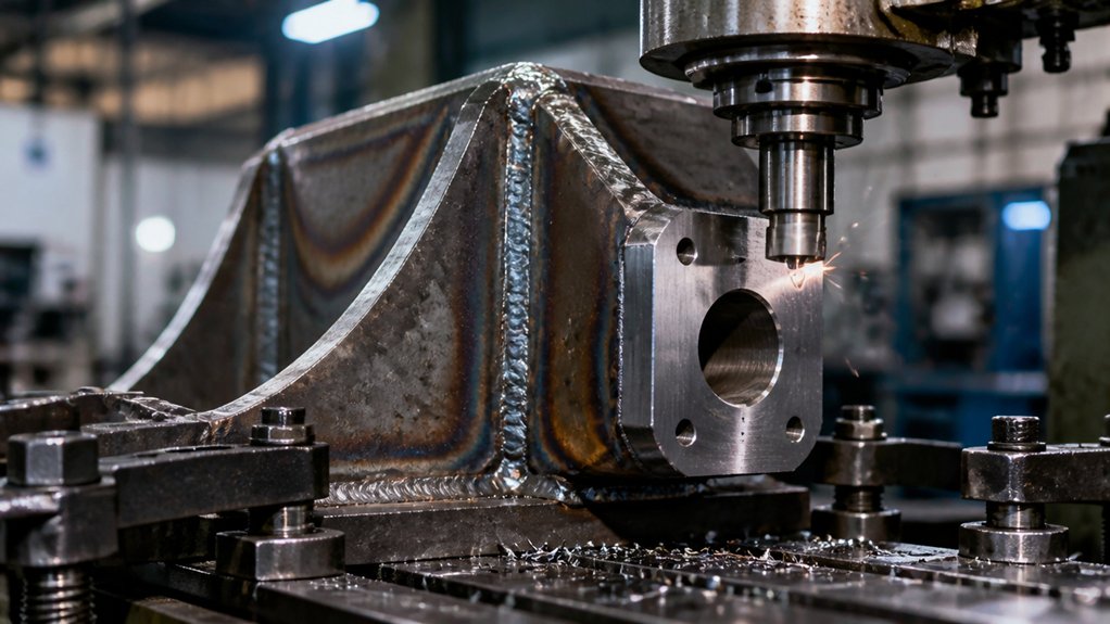
Post-weld machining is needed when inspection shows that a welded part no longer meets its drawing requirements for alignment, fit, or surface finish. Welding can distort a mounting face, move holes, or shift bearing seats as the assembly cools.
Before machining, check the welds and confirm that enough material remains to produce the required features. Weld inspection can identify defects that machining will not correct; dimensional inspection shows which surfaces or holes have moved. If the welds are unsound or the part lacks machining allowance—the extra material left for later cutting—the part may not be recoverable.
The machining plan should identify a datum, a reference surface or feature used to locate and measure the part, and set the order of operations. The best datum and sequence depend on the drawing tolerances, the part’s geometry, its material, and how it will be held during machining. For example, machining a mounting face before boring a bearing seat can help keep the seat aligned to that face, if the setup locates the part reliably. The drawing and inspection plan should specify which features are critical and how they will be checked after machining.
When Does a Welded Part Need Machining?
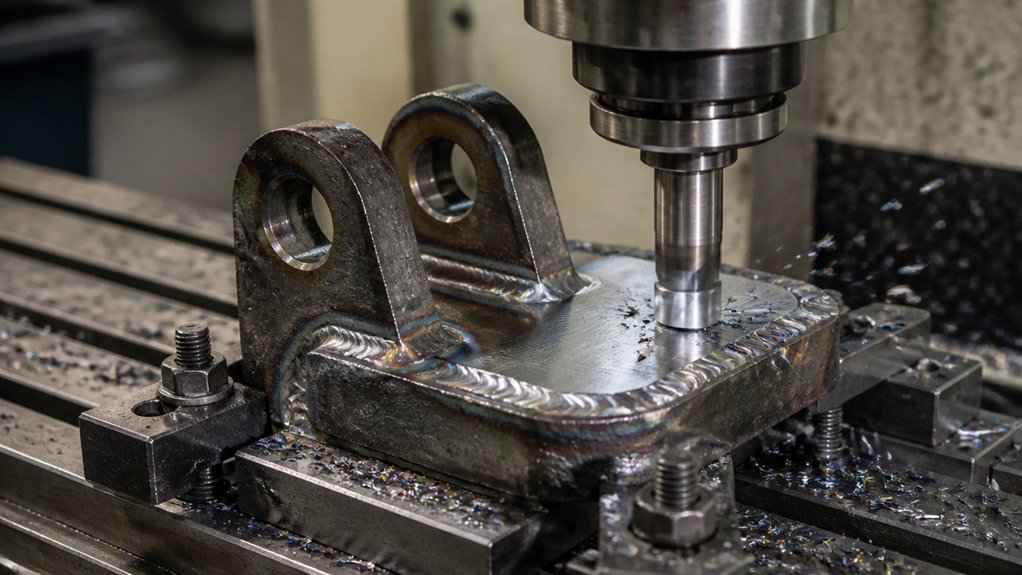
A welded part needs machining when welding leaves a critical surface or feature outside the drawing’s tolerance—the permitted variation in its size, shape, or position. Check dimensions after welding, because heat can distort nearby features as well as the joint itself.
Compare the inspection results with the requirements for fit, alignment, sealing, and service. For example, a warped mounting face may need milling, while a bore shifted by welding may need boring if enough material remains. Milling removes material with a rotating cutter; boring enlarges or corrects an existing hole with a cutting tool.
Machining may also remove weld spatter or excess weld metal when it prevents contact or clearance. Don’t remove material from a weld or heat-affected zone—the area of base metal changed by welding heat—without checking the drawing and applicable weld requirements. The decision depends on the base metal, weld design, feature tolerance, and material available for correction; machining mustn’t reduce the part below its required dimensions or compromise weld strength.
When Should You Do Post-Weld Machining?
Schedule post-weld machining after the welded assembly has cooled and stabilized, and after required weld inspections are complete. Welding can distort a part, so machining too early may leave bores, faces, or mounting surfaces out of position as the assembly settles. The right timing depends on the material, weld sequence, part geometry, and drawing requirements.
> Let the welded assembly cool, stabilize, and pass required inspections before machining to avoid distortion-driven misalignment.
Before releasing the job, compare the assembly with the drawing. Confirm the datum surfaces—the reference points used to locate and measure the part—and check machining stock, tool access, and clamping locations. Stock allowance is the material intentionally left for machining. Make sure enough remains to finish each feature without cutting into required weld metal.
Plan the machining sequence around stable locating surfaces. Machine reference surfaces first, then finish close-tolerance bores, faces, and threads from those references. The drawing should state required dimensions and surface finish, which describes how smooth a machined surface must be. Verify both after machining.
For weld repair, agree on removal limits with the welding and quality teams before cutting. If machining reveals movement or would exceed approved repair limits, stop and obtain engineering approval. Record inspection results, measurements, drawing revisions, and final dimensions for traceability.
How Welding Can Change Part Dimensions
Welding can change a part’s dimensions by causing the metal near the weld to expand during heating and contract as it cools. In gas metal arc welding (GMAW) of steel plate, this uneven contraction can pull edges together, bend a plate, or shift holes and other features. The amount and direction of movement depend on the steel grade and thickness, joint design, weld size, heat input, and welding sequence.
Distortion is the unwanted change in shape or position caused by welding. Long, thin plates and parts with welds on only one side are more prone to bending or twisting than short, balanced assemblies. A fixture—a device that holds parts in position—can restrain movement during welding, but the part may move when it’s released. Stresses left in the metal after cooling can also cause movement during later machining.
For a production drawing, identify critical dimensions and feature locations, and specify the required tolerances. Agree on the measurement method and inspection stage, since readings taken while the part is hot or clamped may not show its final shape. Check the assembly after it has cooled to a stable temperature and the clamps are released. If a dimension is out of tolerance, review the weld sequence, restraint, and machining plan before deciding how to correct it.
Which Welded Features Need Post-Weld Machining?
Post-weld machining is usually needed on welded features that locate, seal, rotate, or mate with another part, when the as-welded feature doesn’t meet the drawing requirements. The need depends on the feature’s function, specified tolerances, material, weld process, and the distortion caused by welding.
Common examples include bearing seats, shaft bores, mounting faces, gasket lands, and precision holes. A bearing seat supports a bearing; a gasket land is the surface compressed against a gasket to prevent leakage. These surfaces may need machining to meet specified dimensions, flatness (how closely a surface lies in one plane), roundness, or surface finish (the texture of the surface).
Threads, counterbores (larger recesses around holes), and reference datums (surfaces or points used to measure other features) may also need repair if weld metal or heat affects them. The drawing should identify machining allowances—the extra material left for later removal—and inspection requirements. If it does not, the buyer or engineer should clarify them before fabrication.
Not every weld needs machining. An as-welded surface can remain untouched if it meets the drawing and service requirements. Before specifying material removal, check whether it would reduce wall thickness or weaken a load path, the route through which a part carries force. The amount of machining also depends on access, material, and how much weld distortion must be corrected.
How Can You Control Distortion and Hold Tolerances?
Control weld distortion and hold tolerances by agreeing on the weld sequence, fixture plan, machining allowance, and inspection points before production. The right plan depends on the part’s geometry, material, thickness, joint design, and required finished dimensions.
For a welded steel assembly, specify a balanced weld sequence so heat and shrinkage are distributed across the part. Short, alternating weld passes can limit heat buildup; the suitable pass length and cooling interval depend on the welding process, steel grade, thickness, and joint. A fixture is a device that holds parts in position during welding. Locate it from stable datums—reference surfaces used to position and measure the part—but avoid restraining the assembly so tightly that weld shrinkage creates stress or movement when it’s released.
Set inspection points for the as-welded part, after unclamping, and after machining. This helps identify springback, the movement that occurs when a restrained part is released. Budget tolerances by separating acceptable as-welded variation from the tighter requirements for finished features. Leave enough machining stock on critical faces to remove distortion, but not so much that machining exposes defects or leaves weak sections. Specify the datums and calibrated measuring equipment for final checks, and use inspection results to revise the sequence or fixture for later production.
Frequently Asked Questions
Can Post-Weld Machining Remove Weld Discoloration or Surface Scale?
Yes. Milling, grinding, or turning can remove weld discoloration and surface scale if the cut reaches below the affected layer. Surface scale is an oxide layer formed by heat; discoloration is a heat-tinted surface that may indicate oxidation.
The result depends on the base metal, weld process, scale depth, and required finish. On stainless steel, machining can remove heat tint, but it also removes the chromium-rich surface layer that supports corrosion resistance. Specify any required post-machining cleaning or passivation, a chemical treatment that helps restore that layer.
Allow enough stock for the cut, and check that removing it will not reduce the part below its drawing dimensions or weaken a thin wall. Tell the fabricator which surfaces may be machined and state the required final dimensions and surface finish. Machining is not a substitute for checking weld quality: it removes surface material but does not establish whether a weld has internal defects.
Which Machining Methods Work Best for Welded Assemblies?
CNC milling is usually the best choice for flat faces, slots and bolt patterns on welded steel assemblies; turning suits round features, while grinding is for surfaces that need a fine finish or close dimensional control. CNC means computer numerical control: programmed instructions guide the cutting machine. These processes remove material from the assembly, so they can correct weld-related variation where the part has enough stock.
The right method depends on the assembly’s shape, material, required fit and drawing tolerances. For example, a welded A36 carbon-steel frame may be milled where mounting pads must sit flat; a round shaft welded into a hub may need turning. Grinding is not a substitute for correcting major distortion or undersized features.
Welding can pull parts out of position as the metal heats and cools. The fabrication plan should specify datum surfaces—the reference faces used to locate and measure the part—and how the assembly will be fixtured, or held in position, during machining. It should also state whether machining happens after welding and stress relief, a heat treatment used to reduce residual stress. Check that the drawing identifies machined surfaces, tolerances, and features that must remain aligned.
How Should Welds Be Inspected Before Machining Begins?
Before machining begins, require the welds to be clean, dimensionally checked, and inspected using the methods specified in the drawing, welding code, or purchase specification. This check can reveal defects or distortion before cutting removes material or makes repair more difficult.
Remove slag, spatter, oil, and paint that could hide the weld surface or interfere with inspection. Check the part’s key dimensions and datum locations against the drawing; a datum is a reference point or surface used for measurement and machining setup. The required dimensional checks depend on the part’s design and machining plan.
Use visual testing to look for surface cracks, undercut, porosity, and incomplete welds. Visual testing means examining the weld surface under suitable lighting. If the specification requires nondestructive testing (NDT)—inspection that does not damage the part—use the named method, such as magnetic-particle testing for surface and near-surface flaws in ferromagnetic steel, or ultrasonic testing for internal flaws. The appropriate method depends on the material, weld geometry, flaw types of concern, and governing code.
Compare findings with the acceptance criteria in the applicable code or specification. Record inspection results, any repairs, dimensional checks, and approval to machine. This gives the machinist a clear basis for setup and helps protect the finished dimensions.
Can Machining Expose Defects Hidden Beneath a Weld Bead?
Yes. Milling or grinding a weld bead can expose porosity, cracks, or lack of fusion at the weld surface or just below it. Porosity is gas trapped in the weld; lack of fusion means the weld metal did not bond fully to the base metal or an earlier weld pass.
Removing the bead does not reveal every internal flaw. A crack or pore may remain below the machined surface, and machining can remove evidence of a surface-breaking defect. The result depends on the weld process, joint design, base-metal grade and thickness, and how much material is removed.
Specify the required inspection method in the drawing or purchase specification. Visual inspection can check the finished surface. Liquid penetrant testing uses dye to find defects open to the surface, while ultrasonic testing uses sound waves to detect some internal flaws. The suitable method depends on the material, joint geometry, flaw type of concern, and acceptance criteria. For critical parts, require inspection after machining, since machining may expose flaws that were not visible on the original weld bead.
What Information Should a Machinist Receive About the Welding Process?
Before machining a welded part, obtain the approved welding procedure specification (WPS), which states how the joint is to be welded, and the records showing how the work was done. The information should identify the welding process, base-metal grade and thickness, filler-metal classification, joint details, and any required preheat or post-weld heat treatment. These details help the machinist choose suitable cutting tools and avoid removing material that the design needs.
Ask for the weld sequence and heat-input records, too. Heat input is the energy applied during welding; it can affect distortion and the properties of the heat-affected zone, the base metal changed by welding heat. The right machining allowance and sequence depend on the part’s geometry, material, weld location, and final tolerances. Confirm which dimensions are critical and whether they refer to the part before or after welding.
Request inspection records for required visual, dimensional, or nondestructive examination, such as radiography or ultrasonic testing. Also verify that the welder’s qualifications cover the process and material used, as required by the job’s governing code or specification. These checks help identify defects or dimensional changes before machining makes correction harder.