
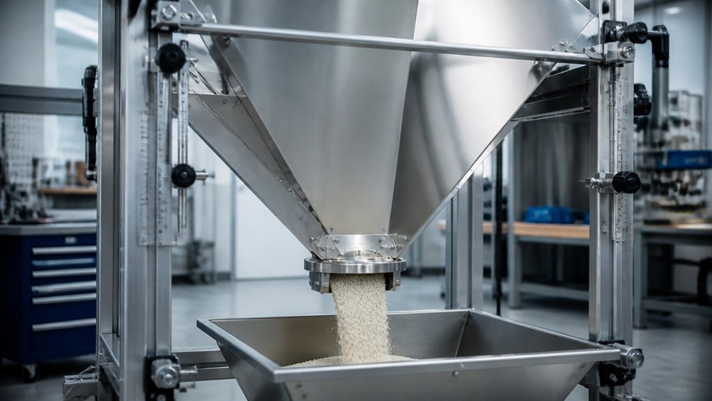
A hopper’s wall angle and outlet size should be based on tests of the bulk material and the required flow pattern. Wall friction is the resistance between the material and the hopper surface; cohesion is the tendency of particles to stick together. Test representative samples for wall friction, moisture, cohesion, and particle shape under expected operating conditions.
Use the results to choose the wall angle, outlet dimensions, and surface finish. A mass-flow hopper moves material along the full wall surface, while a funnel-flow hopper lets material move mainly through a central channel. The suitable pattern depends on the material’s flow properties and the process requirements. For a metal hopper, the surface may be carbon steel or stainless steel, but the grade and finish should suit the material, moisture, wear, and cleaning needs.
A design can still bridge, where material forms an arch over the outlet, or rathole, where a stable channel empties while material remains around it. Ask the fabricator to document the design basis, including material test conditions, wall angle, outlet size, plate grade and thickness, and specified welds. Cost depends on the hopper’s dimensions, plate material and thickness, forming and welding requirements, surface treatment, and any supports or flow aids.
Assess Material Flow for Hopper Design
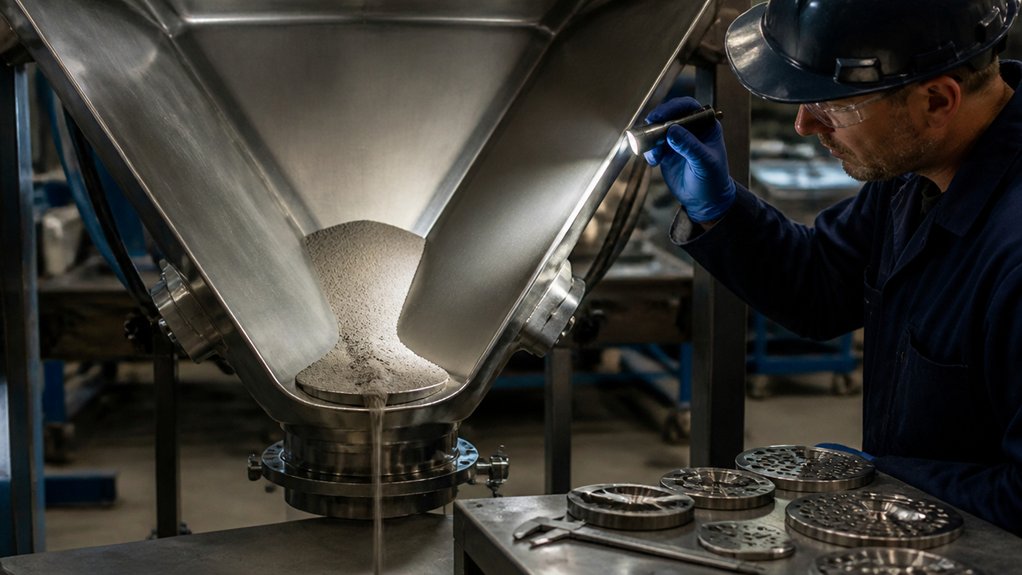
Assess hopper flow using the actual bulk material and expected storage conditions before setting the outlet or wall angles. Particle size distribution, moisture, bulk density, and the tendency to compact or cake affect whether material discharges evenly or leaves stagnant zones.
Use samples that represent the material’s expected range, including changes in moisture, temperature, and particle shape. Measure wall friction, the resistance between the material and the hopper surface, and internal friction, the resistance between particles. Test how consolidation—the strengthening that can occur under storage pressure—changes the material’s flow strength. Supplier data can help, but it may not reflect the conditions in the finished system.
Choose between mass flow, where material moves across the hopper’s full cross-section, and funnel flow, where material moves mainly through a central channel, based on discharge needs. Consider segregation, residue, and feed consistency. The right pattern depends on the material, hopper surface, and process requirements. Use the assessment to identify risks of bridging, where material arches over the outlet; ratholing, where a channel empties while material remains around it; and buildup on the walls. These findings inform hopper geometry and blockage controls.
Set Hopper Wall Angles and Outlet Size
Set the hopper wall angle and outlet size from flow tests on the specific bulk material and the proposed lining, rather than from a general rule. The wall angle is the slope of the hopper surface; the outlet is the opening through which material leaves. A steeper wall may help material slide, but the required angle depends on friction against the lining, moisture, cohesion, and particle shape.
Specify the lining material and surface finish, then ask for test data that reflects those conditions. For example, test the intended grade and particle form of iron ore or plastic pellets at the moisture level expected in production. The results can help determine whether the design needs a mass-flow pattern, in which material moves across the full hopper, or whether stagnant zones may remain.
Size the outlet to pass the largest particles and sustain the required discharge rate without bridging, a blockage across the opening, or ratholing, a flow channel surrounded by stagnant material. Confirm the proposed dimensions against the feeder and downstream equipment. Require discharge testing with a representative sample, and record the material condition, lining, geometry, and operating settings so results can be compared consistently. Adjust the design if tests show residue, surging, or blockage.
Choose a Flow Pattern for Reliable Discharge
Choose the flow pattern by matching the hopper’s geometry and wall surface to the material’s flow properties and the required discharge behavior. In mass flow, all material moves when product leaves the outlet. This pattern supports first-in, first-out turnover and limits stagnant material, but it depends on the material’s friction against the hopper walls and the hopper’s slope.
Funnel flow forms a moving channel above the outlet while material near the walls stays in place. It may suit free-flowing material when stagnant zones are acceptable, but those zones can cause segregation or spoilage. The outlet and hopper shape must support the intended pattern and avoid pockets where material can collect.
Before specifying a hopper, identify the stored material, its flow behavior, how long it will remain in storage, and how sensitive it’s to contamination or aging. Ask the hopper designer to base wall angles and surface selection on measured material properties, not assumptions. The right pattern depends on the material, required throughput, storage time, and discharge consistency.
Test Discharge and Fix Common Blockages
Confirm reliable hopper discharge by testing the specified bulk material under the moisture, temperature, and fill-level conditions expected in service. Record the discharge rate, material left behind, and any interruptions. These results help determine whether the outlet and wall design suit the material; hopper performance depends on its flow properties and operating conditions.
If flow stops, check for bridging: a stable arch of material across the outlet. If an arch forms, assess whether the outlet needs to be larger; vibration may not resolve an opening that’s too small. Ratholing occurs when material flows through a narrow channel while the rest remains in place. Steeper walls or a mass-flow design, which moves material across the full hopper cross-section, may help. The right change depends on the material’s flow behavior and hopper geometry.
Also inspect for buildup, rough surfaces, and air leaks, which can promote sticking or uneven flow. Change one design or operating variable at a time, then repeat the test. Record the results so the production team can verify consistent discharge before approving the design.
Frequently Asked Questions
What Materials Are Commonly Used to Construct Hoppers?
Hoppers are commonly fabricated from carbon steel, stainless steel, aluminum, or abrasion-resistant steel. The right choice depends on the material being handled, exposure to moisture or chemicals, impact and wear, and the hopper’s support requirements.
Carbon steel is a common choice for dry, noncorrosive products. It can be cut, bent, and welded, then protected with paint or a replaceable liner. Stainless steel is often specified when corrosion resistance or cleanability matters; the required grade depends on the product and cleaning chemicals. Aluminum weighs less than steel, but its lower stiffness and different welding requirements can affect the design.
Abrasion-resistant steel can help where bulk solids wear against the hopper walls. It is harder to form and weld than ordinary carbon steel, so the fabricator should confirm the grade’s processing requirements before detailing seams and openings. Liners made from materials such as polyurethane or stainless steel can protect the shell or reduce sticking, but they must suit the product and operating conditions.
When reviewing a fabrication drawing, check the material grade, plate thickness, weld locations, surface finish, and coating or liner specification. Also confirm that the design accounts for the product’s weight and flow behavior.
How Often Should a Hopper Be Inspected for Wear?
Inspect a hopper at least monthly, and inspect it more often when it handles abrasive or corrosive material or runs at high volume. The right interval depends on the material, operating hours, flow rate, and the hopper’s construction.
Look for thinning, cracks, deformation, and loose or damaged connections. Focus on outlets, seams, and impact zones, where material flow and repeated impacts can cause wear. For steel hoppers, check for corrosion as well as wear; for lined hoppers, check that the lining is not cracked, detached, or worn through.
Record each inspection, including the location and type of damage, so changes can be tracked over time. Inspect the hopper after unusual conditions such as a blockage, an impact, or a change in the material being handled. If an inspection finds damage, have a qualified person assess whether the hopper can continue operating safely and whether repair or replacement is needed.
Can Hopper Liners Reduce Corrosion or Abrasion?
A hopper liner can reduce corrosion or abrasion by separating the hopper shell from corrosive material or sliding solids, but it does not eliminate damage. The right liner depends on the material being handled, its moisture and chemistry, particle size and shape, impact, flow rate, and cleaning method.
For corrosion, compare the process material with the liner manufacturer’s chemical-resistance data. Stainless steel, such as 316L, may suit some wet or chemical services; polymer liners such as polyethylene may suit others. Neither is universally resistant, and seams, fasteners, and cut edges can remain vulnerable.
For abrasion, consider abrasion-resistant steel plate or a replaceable polymer liner. Abrasion-resistant plate resists wear but adds weight and may be harder to cut and weld than mild steel. Polymer can reduce friction and protect the shell, but impact, heat, chemical exposure, and attachment details can limit its use. Confirm compatibility and operating limits in the selected manufacturer’s data.
When specifying the liner, identify the hopper’s base material, process conditions, attachment method, and areas of concentrated wear. Check that the design avoids gaps where material can collect and allows inspection or replacement. Regularly inspect seams, fasteners, and exposed shell for wear, corrosion, or liner movement.
What Safety Precautions Apply During Hopper Maintenance?
Before hopper maintenance, isolate and lock out every energy source, verify that the equipment cannot start or release stored energy, wear the required protective gear, and control access to any confined space. Lockout/tagout means applying locks and warning tags to energy-isolating devices so equipment cannot be restarted during work.
The maintenance plan should identify electrical, hydraulic, pneumatic, gravity, and process hazards that apply to the hopper. Workers should follow the equipment maker’s instructions and the site’s energy-control procedure. A zero-energy check must confirm that moving parts are stopped and that pressure, suspended loads, and material flow cannot create a hazard.
If entry into the hopper is required, assess whether it meets the applicable confined-space rules. A confined space is an area with restricted entry or exit that is not designed for continuous occupancy. Entry controls may include atmospheric testing, ventilation, an attendant, communication, and a planned rescue method; the required controls depend on the hopper and the hazards present. Practice emergency communication and rescue procedures before work begins, and do not rely on an improvised rescue.
How Can a Hopper Be Integrated With Automated Controls?
A hopper can be integrated with automated controls by connecting its sensors and discharge equipment to a programmable logic controller (PLC), an industrial computer that runs equipment sequences. The PLC can use level sensors to detect how much material is in the hopper, flow sensors to detect movement, and blockage sensors to flag a jam. Sensor choice depends on the material’s size, dust, moisture, and tendency to bridge or stick.
The control sequence should coordinate the hopper’s discharge with upstream and downstream equipment. An interlock is a control rule that prevents one machine from running unless another is ready; for example, the PLC can stop feed when a conveyor is unavailable. The brief should specify what each sensor detects, what action follows an alarm, and whether operators can run equipment manually.
Include safe maintenance modes in the control design. These modes should prevent unexpected startup during inspection or clearing, using the site’s required isolation and lockout procedures. Final wiring, control logic, and safety functions depend on the hopper layout, connected machinery, material hazards, and applicable electrical and machine-safety requirements.