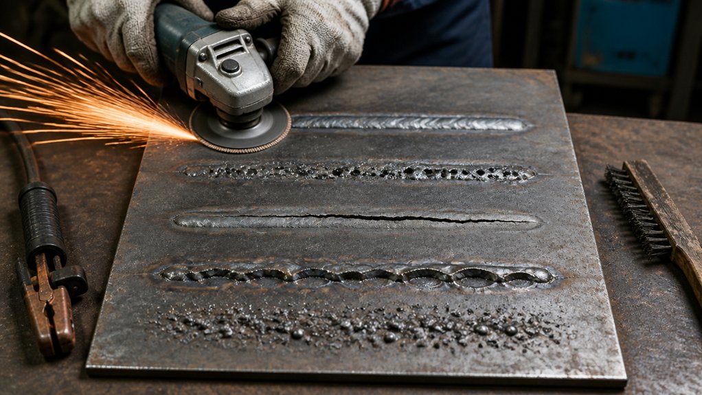
Porosity, cracks, undercut, and incomplete fusion are common weld defects; preventing them starts with clean material, correct fit-up, and settings suited to the specified welding process and metal. For example, gas metal arc welding (GMAW) on carbon steel needs clean joint surfaces and shielding gas that is not disrupted by drafts. Fit-up means how the parts align and how wide the gap is between them.
Porosity is trapped gas in the weld. Remove oil, paint, rust, and moisture, and check gas flow and nozzle condition. Cracks can result from restraint, unsuitable filler metal, or a cooling rate that is too fast; the cause depends on the base metal, joint design, and welding procedure. Undercut is a groove melted into the base metal beside the weld. It can result from excessive heat or travel speed, so check the procedure settings and the finished weld profile.
Incomplete fusion means the weld metal did not bond fully to the base metal or previous weld pass. Check joint access, surface preparation, and heat input—the energy delivered during welding. Before production, the buyer or engineer should specify the material grade, thickness, joint design, welding process, and applicable acceptance standard. Require defects to be removed and repaired under an approved procedure, then inspected; covering a flaw with another pass can hide it without correcting the cause.
Identify and Prevent Weld Porosity
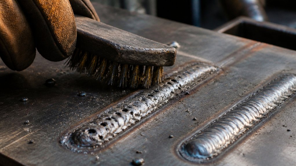
Spot weld porosity by looking for pinholes or cavities in the weld bead, but a smooth surface doesn’t rule out internal voids. Porosity is gas trapped as the weld metal cools. Internal defects may require a suitable inspection method, such as radiographic or ultrasonic testing; the choice depends on the joint, material, and inspection requirements.
For gas metal arc welding (GMAW) of carbon steel, ask the fabricator to check shielding-gas connections and flow, protect the arc from drafts, and keep the wire and joint clean and dry. Shielding gas protects the molten weld pool from air. Moisture, oil, rust, paint, and mill scale can introduce gas or interfere with that protection. The required gas and filler wire depend on the steel grade, thickness, joint design, and applicable welding procedure.
Review the joint design for access and a clear path for gas to escape. Travel speed and heat input—the energy delivered to the weld—should keep the molten pool stable without excessive heating or rapid cooling. Ask for settings to be checked on representative scrap, then have the fabricator record the procedure and inspection results so recurring pores can be traced to their source.
Find and Repair Weld Cracks Safely
Find and repair a weld crack by taking the part out of service, identifying the crack’s full extent, removing it completely, and rewelding under an approved repair procedure. A weld toe is where the weld meets the base metal; cracks can also start at the root, the joint’s interior, or at a crater, the end of a weld bead. Even a short crack can grow under load.
Inspect the joint under good lighting. If the crack’s limits are unclear, use dye penetrant testing, which reveals surface-breaking flaws, or another nondestructive testing method suited to the material and joint. Mark the crack ends, then have a qualified welding engineer or inspector assess the joint’s function, material grade, thickness, and governing code before repair.
Secure the assembly against movement, let it cool, remove nearby coatings, and provide ventilation. Use protective equipment suited to grinding and welding. Grind out the crack and a small amount of surrounding metal; verify removal with an appropriate inspection method before rewelding. Follow the specified welding process, filler metal, heat control, and weld sequence. Inspect and document the repair. Never weld over a crack, because the flaw may remain beneath the new weld.
Prevent Undercut in Your Welds
Prevent undercut by matching the welding procedure to the base metal and joint, then controlling heat input, travel speed, and torch or electrode position. Undercut is a groove melted into the base metal beside the weld that the weld metal doesn’t fill. It can reduce the joint’s effective thickness and create a stress concentration.
For a production brief, specify the welding process, base-metal grade and thickness, joint design, filler metal, and applicable acceptance standard. The right amperage and travel speed depend on these details, as well as the welding position and equipment. Excessive heat or fast travel can leave the weld toe—the edge where the weld meets the base metal—unfilled. The qualified welding procedure should set the required parameters.
Ask the fabricator to clean the joint, use the specified procedure, and inspect both weld toes after each pass. Visual inspection can identify visible grooves; acceptance limits depend on the governing code or project specification. If undercut exceeds those limits, require repair using an approved procedure and reinspection. Grinding may be part of the repair, but the method mustn’t reduce the base metal below the specified thickness.
Improve Weld Fusion and Penetration
Improve weld fusion and penetration by specifying a qualified welding procedure for the base-metal grade, thickness, joint design, and welding process. Fusion is the joining of the weld metal to the base metal; penetration is how far the weld extends into the joint. The procedure should identify the filler metal, joint preparation, and permitted settings for current, voltage, and travel speed.
For a carbon-steel joint made with gas metal arc welding (GMAW), for example, the correct wire and settings depend on the steel grade, thickness, joint type, and shielding gas. Remove rust, oil, paint, and other contaminants from the joint. Specify the root opening—the gap between the parts—and bevel angle according to the joint drawing and qualified procedure; don’t use a generic dimension.
During production, check that the arc reaches both sidewalls and that travel speed and heat input stay within procedure limits. Too little heat or excessive travel speed can cause incomplete fusion; too much heat can cause burn-through or distortion. Ask for visual inspection and, where the drawing or applicable code requires it, nondestructive testing such as radiography or ultrasonic testing.
Keep filler metal dry and shielding-gas flow stable to reduce porosity, or gas cavities in the weld. Require cracks to be assessed and repaired under an approved procedure, not covered with another pass. Control arc length, electrode angle, and travel speed to limit undercut, a groove melted into the weld toe.
Frequently Asked Questions
How Can I Prevent Weld Spatter From Sticking to My Workpiece?
To reduce weld spatter on carbon-steel parts joined by gas metal arc welding (GMAW), clean off oil, rust, paint, and moisture, then set the wire-feed speed, voltage, and electrode stickout for the wire and material thickness. Spatter forms when the arc is unstable or the weld pool ejects droplets; settings depend on the welding machine, wire type and diameter, shielding gas, joint design, and position.
Keep the arc length—the distance from the wire tip to the workpiece—consistent, and use the shortest arc that produces a stable weld. Follow the wire and power-source manufacturers’ setup guidance, and check the weld procedure before changing settings. A setting that works for one thickness or joint may cause spatter or poor fusion on another.
Anti-spatter spray can limit droplets from sticking, but confirm it is compatible with the base metal, coating, and any later painting or plating. Apply it only where needed and keep it away from surfaces that must be welded; residue can contaminate a weld. Include spatter removal and inspection in the production plan, especially where weld appearance or fit-up matters.
What Causes Excessive Weld Distortion, and How Can I Minimize It?
Excessive weld distortion comes from uneven heating and cooling, which cause the metal to expand and then shrink by different amounts. Thin sheet and long welds are especially prone to warping, but the risk depends on the material, thickness, joint design, weld size, and heat input.
To limit distortion, specify a welding process and sequence suited to the part. For example, a fabricator may use short, alternating welds on opposite sides of a joint rather than completing one long weld in a single direction. The right sequence depends on access, joint strength requirements, and the part’s geometry.
A fixture holds parts in position during welding, but it must allow for shrinkage; excessive restraint can cause residual stress or cracking. The drawing or purchase specification should identify critical dimensions and flatness requirements after welding, along with any required inspection method. Ask the fabricator to document the proposed weld sequence, fixturing approach, and inspection plan. These details help buyers and engineers assess whether the process can control distortion without adding unnecessary weld metal or machining.
How Do I Remove Slag Trapped Between Weld Passes?
Remove trapped slag before depositing the next weld pass. Slag is the nonmetallic residue left by flux-cored arc welding or shielded metal arc welding; if it remains in the joint, the next pass can trap it and create an inclusion.
For a carbon-steel weld, chip away the deposit with a chipping hammer, then use a wire brush to clear loose residue. Use a grinder if slag is firmly attached, taking care not to gouge the base metal or change the joint profile. The appropriate tool depends on the joint shape, access, weld process and material.
Inspect the full groove and the edges of the previous pass under good lighting. Remove any remaining slag and debris before welding again. If the surface is difficult to inspect or the weld is subject to specified acceptance criteria, follow the project’s welding procedure and inspection requirements; these may call for additional examination. Do not deposit another pass over visible residue.
When Should I Grind Down a Weld Bead That’s Too Large?
Grind an oversized weld bead only after it has cooled enough to handle safely, and only if the drawing, weld specification, or inspection plan allows material removal. A weld bead is the deposited metal that forms the visible weld. Grinding it before another pass may change the joint shape or remove metal needed for the next pass.
The permitted profile depends on the joint design, base metal, weld process, and applicable acceptance standard. For example, a fillet weld—the roughly triangular weld joining two surfaces—may need to retain a specified throat, or effective weld thickness. A butt weld joining edges may require a flush surface, but grinding must not reduce the base-metal thickness or create a sharp notch.
Use a grinder suited to the material, such as carbon steel or stainless steel, and keep the abrasive separate when contamination could affect corrosion resistance. After grinding, check the weld profile and surrounding surface against the drawing and inspection criteria; look for undercut, cracks, or gouges. To prevent repeat rework, review the welding procedure and pass sequence, since excess buildup can result from settings, travel speed, or joint preparation.
How Can I Tell Whether a Weld Has a Poor Surface Finish?
A poor weld surface may show undercut, porosity, cracks, excessive spatter, or an uneven bead. Undercut is a groove melted into the base metal beside the weld; porosity is a cluster of small holes. These defects can weaken a joint, but appearance alone does not establish whether a weld is acceptable.
Inspect the weld under good lighting and compare it with the drawing, purchase specification, and acceptance standard named in the contract. Check for visible cracks, sharp transitions, incomplete coverage, and bead shape that varies from the specified profile. A smooth-looking surface does not prove that the weld has adequate penetration, meaning fusion through the required joint depth.
The right acceptance criteria depend on the welding process, base material and grade, thickness, joint design, and service conditions. For example, a visible surface check on a gas metal arc weld in carbon-steel plate cannot confirm internal soundness. If the specification requires it, a qualified inspector can use methods such as dye penetrant testing, which reveals surface-breaking flaws, or radiographic testing, which checks for some internal defects.