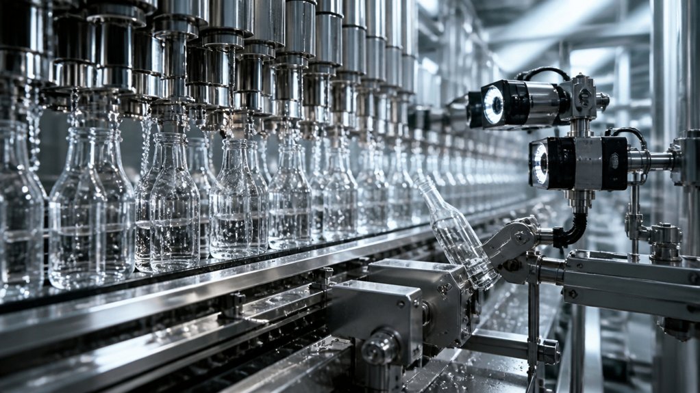
Vision inspection can reduce bottlenecks in metal fabrication by finding defects early and sending useful process data to machine controls. A vision system uses cameras and image-processing software to check parts for features such as hole location, edge condition, weld presence, or surface defects.
For laser-cut parts made from ASTM A36 steel sheet, inspection can compare hole and profile locations with the drawing before parts move to bending or welding. The required tolerance depends on the drawing, material thickness, cutting process, and how the part fits with adjoining components. Do not assume that a camera can verify every requirement: surface finish, internal weld quality, and some dimensional features may need other inspection methods.
Inspection data can help operators adjust a laser cutter, press brake, or conveyor when repeated errors point to a process drift. A programmable logic controller (PLC) is an industrial computer that coordinates equipment; it can use sensor and inspection signals to slow, stop, or redirect parts. When briefing a supplier, specify the material grade and thickness, critical dimensions, defect criteria, inspection points, and how rejected parts should be handled.
Common Bottling Line Bottlenecks
Metal fabrication loses time most often at handoffs between cutting, forming, welding, and finishing, where parts may wait, need rework, or fail to fit the next operation. The risk depends on the material, part geometry, tolerances, and how the job is routed through the shop.
For a sheet-metal enclosure made from 5052-H32 aluminum, for example, the drawing should identify the alloy and temper, sheet thickness, bend locations, and required dimensions. A bend allowance—the material length used to form a bend—depends on thickness, tooling, and bend radius, so the fabricator should confirm it before cutting. Unclear dimensions or unspecified inside radii can lead to parts that don’t assemble.
Welded assemblies can also become bottlenecks when the drawing doesn’t define weld locations, joint preparation, or the required inspection. A fixture, which holds parts in position during welding, can reduce movement, but its design depends on the assembly and the welding process. For a machined interface, specify which surfaces control fit and how they’ll be measured.
Before work begins, check the drawing revision, material certification requirements, finish, and inspection method. Ask how parts move between operations and which features are checked before the next step; this can reveal likely delays without assuming that faster equipment alone will solve them.
How Vision Systems Spot Bottle Defects
Machine-vision inspection can check metal parts for dimensional errors and visible surface defects before they move to the next operation. Cameras capture the part, and image-processing software compares its edges, holes, welds, or surface against the inspection criteria in the drawing or quality plan. A dimensional tolerance is the permitted variation from a specified measurement; the drawing should define it for each feature that matters to fit or function.
The inspection setup depends on the material, finish, part geometry, and defect type. Backlighting can make a cut edge or hole easier to measure, while angled lighting can reveal scratches, burrs, or weld irregularities. Reflective stainless steel may need diffuse lighting to reduce glare; dark coatings may need a different light and camera exposure. The inspection plan should state which defects are rejectable and how the system handles features hidden from the camera.
Inspection records can help identify recurring problems, but they don’t establish the cause by themselves. A pattern of out-of-position holes, for example, may warrant checks of the cutting program, fixture, or sheet movement. Buyers and engineers should confirm that the inspection method covers critical features and that results are traceable to the part or production lot.
How Automation Keeps Bottles Moving
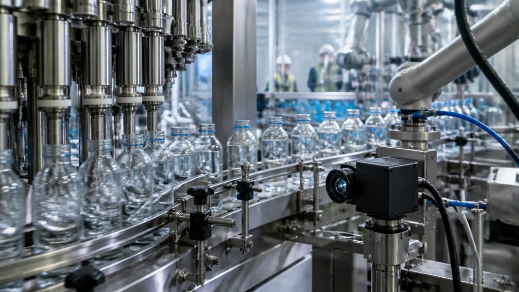
Automation keeps bottles moving by coordinating conveyors, sensors, and programmable logic controllers (PLCs), which are industrial computers that control equipment. On a metal fabrication line, the same approach can move steel or aluminum parts between cutting, forming, welding, and finishing stations.
Variable-speed drives adjust conveyor motor speed to match each station’s cycle time. Photoelectric sensors detect whether a part is present and signal a transfer or stop. The right setup depends on part dimensions, weight, surface condition, and the handling needs of each process. For example, a conveyor suited to flat sheet may not support a long, narrow part without additional guides.
A PLC can coordinate motors, gates, and indexing mechanisms, which advance parts in set steps. Accumulation zones provide temporary space between stations when one process runs more slowly than the next. This can reduce stoppages, but the layout must prevent parts from colliding, tipping, or damaging finished surfaces.
When briefing a system supplier, specify the material, part geometry, maximum load, and required sequence of operations. Check that guides, transfer points, and sensor locations suit the actual parts, and confirm how the controls respond to a jam or missing part. Throughput depends on the slowest station as well as conveyor speed, so faster transport alone may not increase output.
Use Inspection Results to Adjust the Line
Inspection results help identify which metal-fabrication operation needs correction before a defect repeats. For a laser-cut 304 stainless-steel plate, for example, check whether a dimensional error comes from the cut path, sheet movement or part measurement; 304 is a stainless-steel grade designation. Record the drawing revision, material grade and thickness with each inspection result so the production engineer can trace the finding to the right part and process.
Link each result to the operation that could cause it, such as laser cutting, press-brake forming or welding. A press brake bends sheet metal, while welding joins metal parts with heat. If a bent flange is out of position, review the bend setup and measurement method before changing the cutting program. The appropriate correction depends on the part geometry, material condition, machine setup and drawing requirements.
Set acceptance limits from the approved drawing, applicable product standard or buyer specification; don’t substitute a general shop tolerance. Use a feedback loop—a process that returns inspection findings to production controls or operator displays—to flag out-of-limit parts and verify the correction on subsequent pieces. Keep the change limited to the operation linked to the defect, and document the result so downstream work doesn’t conceal or compound the problem.
Measure Bottling Line Performance and Downtime
Measure metal fabrication performance by tracking output, cycle time, defects, and downtime at each production stage. Cycle time is the time needed to complete one operation. For a job involving laser cutting, press-brake forming, and welding, record results separately at each process so a slow or unreliable stage doesn’t disappear inside the total job time.
Compare actual output with the planned rate for the specific part, material, and process. A laser cutting rate depends on factors such as sheet thickness, alloy, cut geometry, and nesting—the arrangement of parts on a sheet. Track machine stops, slow cycles, rejected parts, and setup changes with timestamps. A defect rate is the share of parts that fail inspection; define the inspection criteria on the drawing or purchase specification.
Classify each interruption by cause, duration, and affected equipment. Separate planned maintenance and scheduled changeovers from unplanned stops, then rank losses by total time and frequency. Review results by shift, material grade, part number, and operation to find recurring constraints. Set measurable targets and assign responsibility for corrective actions. Connect inspection records to production output so a rise in weld defects, for example, can be checked against the welding process and the material specification.
Frequently Asked Questions
What Bottle Materials Can High-Speed Bottling Lines Handle?
High-speed bottling lines can handle PET, HDPE, glass, and aluminum bottles, but each line must be configured for the container’s material, shape, and dimensions. PET is polyethylene terephthalate; HDPE is high-density polyethylene. A line designed for one material may need different guides, conveyors, grippers, or inspection equipment to run another reliably.
Material affects how containers behave during filling, capping, and transport. Lightweight plastic bottles can flex under pressure, while glass can break if it collides with other containers. Aluminum bottles may need different handling and inspection arrangements from either material. The required changes depend on bottle geometry, line speed, filling method, closure, and whether containers arrive empty or are formed on the line.
Before specifying a line or a material change, document the bottle’s dimensions, weight, center of gravity, and allowable surface contact. Ask the equipment supplier to confirm compatibility for feeding, filling, closing, labeling, and inspection, then verify it with representative containers. Include changeover time and reject handling in the evaluation, since a line that runs one format well may not maintain the same performance across different materials.
How Much Does a Bottling Vision System Cost?
The cost of a bottling vision system depends on what it must inspect, how quickly the production line runs, and how it connects to existing equipment. A system that checks labels and caps has different camera, lighting, and software needs from one that also detects fill levels or container defects.
Cost drivers include the number of inspection points, the range of bottle shapes and materials, and the difficulty of capturing clear images at line speed. Integration can add work if the system must communicate with a programmable logic controller (PLC), the industrial computer that controls machinery, or trigger a reject mechanism. Installation, operator training, maintenance, and software support also affect the total cost of ownership—the expense of buying, operating, and maintaining the system over time.
When reviewing proposals, compare the inspections each system can perform and the conditions under which its stated accuracy applies. Check whether the quoted scope includes installation, line testing, recipe changes for different products, and ongoing support. A lower initial cost may not cover these items.
Can Existing Bottling Equipment Be Upgraded With Vision Systems?
Yes, existing bottling equipment can often be upgraded with machine vision, a camera-based system that checks products or packaging. Whether a retrofit is practical depends on line speed, available mounting space, lighting, and how the new system can connect to the line’s controls.
For a bottling line, define the inspection task first: for example, checking fill level, cap position, label placement, or printed codes. Each task may need a different camera, lens, lighting, and inspection software. The camera must capture a clear image while bottles move, and the lighting must make the feature being checked stand out.
Check how the system will communicate with the existing programmable logic controller (PLC), the industrial computer that controls machine operations. Confirm what happens when the system detects a defect, such as rejecting a bottle or stopping the line, and whether the equipment has room for a reject mechanism. A controls review can also identify wiring, guarding, and software changes needed for installation.
The right setup depends on bottle shape, label and cap materials, inspection criteria, and production conditions. A trial using representative bottles and packaging can help verify detection performance before the retrofit is specified.
What Training Do Operators Need to Use Automated Bottling Systems?
Operators need training in safe machine operation, the specific fabrication process, quality checks, and routine maintenance. The training should match the equipment and material, such as a press brake forming 304 stainless steel sheet or a CNC laser cutting carbon steel plate.
Operators should learn to read drawings, identify material grades, and check dimensions against the job’s tolerances. A tolerance is the permitted variation from a specified dimension; the drawing or applicable product standard should define it. Training should also cover setup, tool changes, workpiece handling, and inspection methods suited to the process.
Safety instruction should address machine guards, emergency stops, and hazards such as sharp edges, hot work, or laser radiation, as applicable. Operators also need to recognize alarms and follow the manufacturer’s procedures for stopping, clearing, and restarting equipment. Routine maintenance training should cover only tasks operators are authorized to perform; repairs and electrical work may require qualified technicians. The required depth depends on the machine, materials, part complexity, and the operator’s role.
How Often Should Bottling Line Equipment Be Serviced?
For a metal fabrication project, set inspection and maintenance intervals according to the equipment manufacturer’s instructions, the process, and the consequences of a failure. A press brake, which bends sheet metal, needs different checks from a laser cutter or welding system.
Operators should complete the manufacturer’s required pre-use checks and record problems such as unusual noise, leaks, damaged guards, or inconsistent cuts. Schedule deeper inspections based on operating hours and the manufacturer’s maintenance plan; check wear parts, electrical connections, and safety devices. A qualified technician should handle repairs that require specialist training.
Keep records of service, breakdowns, and replaced parts. Use them to spot recurring faults and adjust maintenance timing without skipping required checks. For equipment that could stop production, document which spare parts are critical, where they are stored, and how replacements can be obtained. The right plan depends on machine type, workload, material, and the effect of downtime on production.