

A fabrication prototype starts with a drawing package that defines the part, material, and manufacturing steps. Specify the process, such as laser cutting and press-brake forming, because each process affects achievable shapes, tolerances, and edge conditions.
Name the material grade and thickness, such as ASTM A36 steel plate or 5052-H32 aluminum sheet. State dimensions in inches (millimetres), and identify critical features and their permitted variation; a tolerance is the allowed difference from a specified dimension. Set tolerances according to fit and function, since tighter limits can require more careful processing and inspection.
Include a flat pattern, the unfolded shape used for cutting, and bend details that show bend locations and direction. State the finish, such as powder coating or zinc plating, and identify surfaces that must remain uncoated for electrical contact or welding. Add notes for hardware, weld locations, and any required sequence of operations.
Before approving the first-off—the initial part made from the drawing—check its dimensions, bends, holes, finish, and fit against the specification. Record each defect and determine whether the cause is the drawing, material, tooling, or process before revising the design or build instructions.
Turn Your Sketch Into a Buildable Design
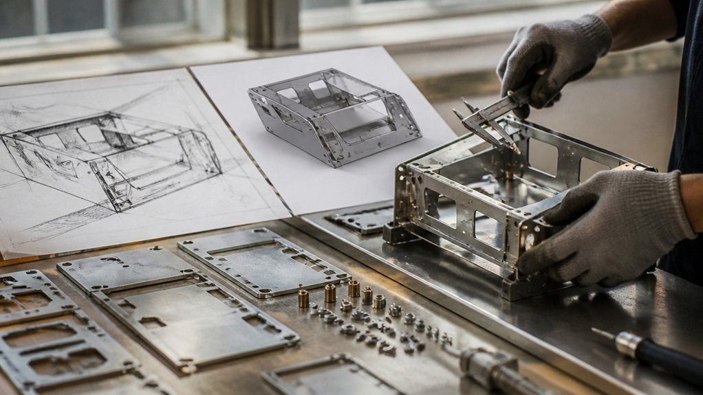
Turn a sketch into a buildable design by documenting its dimensions, material, tolerances, and fabrication processes. A tolerance is the permitted variation in a dimension; set it according to how each feature functions, such as whether a hole must align with another part or a surface is noncritical. Give dimensions in inches with millimetres in brackets, and identify the material grade and thickness when known. If they aren’t yet selected, state the requirements that will guide the choice, such as strength, corrosion resistance, or forming needs.
Create a dimensioned drawing or CAD model that identifies datums—the reference surfaces or features used for measurement—and shows hole locations, bend angles, and mating interfaces. Check tolerance stack-up, meaning the combined variation across related dimensions, where it could prevent assembly. Specify operations such as laser cutting, press-brake forming, machining, welding, or fastening. The suitable process depends on part geometry, material, quantity, and available equipment.
For a production brief, identify setup, tooling, labor, and inspection needs so buyers and engineers can assess the work involved without relying on an unsupported cost estimate. Confirm that the part fits the intended machine envelope and that critical features can be checked with available measuring tools. Issue a controlled drawing package with revision information, and resolve unclear requirements before fabrication starts.
Choose Materials for Your Prototype
Choose a prototype material by matching its grade and thickness to the part’s loads, environment, and fabrication process. For a sheet-metal part made by laser cutting and press-brake forming, compare candidate grades for strength, corrosion resistance, weldability, and formability—the ability to bend without cracking. The right choice depends on the design and how closely the prototype must represent the production part.
For indoor parts with modest corrosion demands, a carbon-steel grade may be suitable; for wet or corrosive service, compare stainless-steel grades such as 304 and 316 against the expected exposure. Aluminum alloys can reduce weight, but their forming and welding behavior differs from steel. Check the material supplier’s data sheet for grade-specific properties, and confirm that the required sheet thickness is available. State thickness in inches (millimetres) on the drawing or purchase specification.
Ask the fabricator to flag features that may distort during cutting or spring back after bending. Springback is the material’s tendency to partly return toward its original shape after forming. Specify the required surface finish, material grade, temper (the condition that affects strength and formability), and any certification requirements. A production-grade match can make performance results more representative; a substitute may be adequate for an early fit check. Lead time and cost depend on stock availability, processing needs, and certification requirements.
Plan and Fabricate the First Prototype
Before releasing a prototype for fabrication, provide a drawing package that defines the part, material, process, and inspection requirements. Include a dimensioned drawing, a flat pattern (the sheet-metal shape before bending), bend details, tolerances, and finish notes. Specify the material grade and thickness, such as 304 stainless steel sheet, and confirm that the supplier can provide it in the required form. Stock availability and the selected process can affect the design.
Review the part for difficult bends, tight features, and operations that could distort it. For a bent sheet-metal part, check that the bend radius and relief features suit the material and press brake tooling; the right choices depend on grade, thickness, and equipment. Set tolerances—the permitted variation in a dimension—to match the function and the capabilities of the proposed process. Avoid specifying tighter tolerances than the design needs.
Compare cutting, forming, joining, and finishing methods based on setup needs, material use, and the number of operations. Plan the sequence and any fixtures, which are supports that locate the part during work, so they hold it securely without blocking tool access. Record process settings and deviations during fabrication. Mark reference surfaces used for measurement, then assemble the prototype and check fit, handling, and intended function before formal review.
Inspect the First-Off and Refine the Design
A first-off matches the drawing when its measured features fall within the approved tolerances and its interfaces fit as specified. A first-off is the initial production part made with the planned process, such as laser cutting and press-brake forming; it isn’t approved by appearance alone.
Compare critical dimensions, hole locations, bend angles, and mating surfaces with the released drawing. Use calibrated measuring tools suited to each feature, such as calipers for accessible dimensions and an angle gauge for bends. Record the actual measurements, the material grade and thickness, and any visible defects or assembly interference. Dimensions should be stated in inches (millimetres); the required tolerances depend on the drawing, process, and function of the part.
Investigate each out-of-tolerance result before changing the design. Check the drawing revision, sheet-metal grade and thickness, machine setup, tooling, and fabrication sequence. A bend-angle error may come from setup or material springback—the tendency of formed metal to partly return toward its original shape—rather than from the design.
For a confirmed design problem, revise the controlled drawing and identify the change. For a process problem, update the work instructions or setup instead. Make another first-off and repeat the same checks; retain the records for approval and production control.
Frequently Asked Questions
How Long Does the Fabrication Prototyping Process Typically Take?
A metal fabrication prototype often takes two to six weeks, but the schedule depends on the part’s design, material, process, and testing needs. A simple sheet-metal bracket cut from commercially available 5052 aluminum may move faster than a welded assembly that needs custom tooling or several fit checks.
The timeline includes more than fabrication. It may cover drawing review, material sourcing, cutting or forming, welding, finishing, inspection, and revisions. A material grade or thickness that is not readily available can add lead time. So can tight tolerances, which are permitted variations in a part’s dimensions, or a design that needs fixtures—tools that hold parts in position during production.
When requesting a schedule, provide a dimensioned drawing, material and grade, thickness, finish, quantity, and required inspection criteria. Ask the fabricator to identify milestones for drawing approval, material arrival, first-article inspection (the check of an initial part), and revision time. Testing requirements and the number of approval rounds can also affect the production handoff date.
What Information Should I Provide When Requesting a Prototype Quote?
For a prototype quote, provide a dimensioned drawing, material and grade, fabrication process, quantity, finish, and required delivery date. A dimensioned drawing shows the part’s measurements and key features; identify whether the part will be laser cut, bent, welded, machined, or made by another process.
Specify the metal by type and grade, such as 6061 aluminum or 304 stainless steel, and state its thickness. Include tolerances—the permitted variation from a stated dimension—only where fit or function requires them. Mark critical dimensions, hole locations, bend directions, welds, and surfaces that must remain free of scratches or scale.
Explain how the part will be used, what it must connect to, and whether it needs to meet a code or industry standard. State the expected load, operating environment, and any required inspection or testing. For assemblies, provide an assembly drawing and note fasteners, joining methods, and parts supplied separately.
The quote depends on material availability, process choice, quantity, finishing, inspection, and how complete the design information is. Flag any open design decisions so they can be resolved before production.
How Much Does a Fabrication Prototype Usually Cost?
A metal fabrication prototype’s cost depends on its material, manufacturing process, design complexity, required tolerances, finishing, and quantity. A one-off laser-cut and bent sheet-metal part has different cost drivers from a machined aluminum block or a welded steel assembly.
Material choice affects both stock cost and how easily a part can be cut, formed, or machined. Specify the alloy and product form, such as 6061 aluminum plate or 304 stainless-steel sheet, rather than just “aluminum” or “stainless.” Include the stock thickness and finished dimensions in inches, with millimetres in brackets.
Tight tolerances—limits on how much a dimension may vary—can require slower machining, extra setups, or inspection. Apply them only to features that affect fit or function. A drawing should also identify weld locations, surface finish, deburring, and any coating or heat treatment.
The estimate can change if the design needs special tooling, purchased components, material certification, or testing. Quantity matters, too: setup work is spread across more parts in a small production run, while a single prototype may carry the full setup burden. Provide a dimensioned drawing and state which features must be checked so suppliers can assess the same scope.
Can I Protect My Design When Sharing It With a Fabricator?
Yes. You can reduce the risk of a fabricator using or sharing your design by setting clear terms before sending files, but no single step guarantees protection.
Ask a lawyer who handles intellectual-property matters which rights may apply. A patent can protect a qualifying invention, while copyright may protect original drawings; neither automatically prevents every use of the underlying product design. A nondisclosure agreement (NDA) is a contract that limits how the recipient may use or disclose confidential information. Have it reviewed before sharing sensitive files.
Send only the information needed for the next manufacturing step. For example, a fabricator quoting a laser-cut 304 stainless-steel bracket may need a dimensioned drawing and material specification, but not the full product assembly. Mark drawings “Confidential” and include revision dates, but treat those marks as reminders, not legal protection. Keep a record of what you sent, when you sent it, and who received it.
Before production, confirm in writing who owns any changes, tooling designs, or manufacturing files created for the job, and whether the fabricator may retain or reuse them. The right terms depend on the design, the work being commissioned, and the parties’ existing agreements.
What Happens After the First-Off Prototype Is Approved?
After approval, transfer the approved prototype requirements into controlled production documents before scheduling the full run. These documents should identify the material grade and thickness, fabrication processes, dimensions, tolerances, finish, inspection requirements, and revision level.
Check that drawings and specifications agree with the approved part. A tolerance is the permitted variation in a dimension; set it according to fit, function, and the capabilities of the chosen process. For example, laser cutting, press-brake forming, and welding can affect dimensions in different ways, so the inspection plan should address the features that matter to assembly and use.
Confirm that the specified sheet, plate, tube, or bar is available in the required grade and thickness, and that the necessary tooling and fixtures are ready. A fixture is a device that holds parts in position during fabrication or inspection. Then agree on production quantity, inspection points, packaging, and delivery timing. Track any change to the drawing or process through a documented revision, and resolve open questions before production begins. These checks help prevent a prototype approval from being mistaken for approval of undocumented changes or uncontrolled production conditions.