
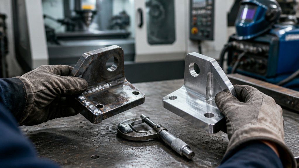
A tolerance that works for a machined feature may not be realistic for a cut, bent, and welded steel part. Machining removes material with a cutting tool, so a shop can control selected dimensions without the heat and forming forces that affect fabrication. Cutting, bending, and welding can move the material or change its shape.
The practical tolerance depends on the process, material, thickness, part size, and how the dimension affects fit or function. For example, a hole location in a machined aluminum bracket may need closer control than the overall length of a welded mild-steel frame. A drawing should identify critical dimensions and distinguish them from dimensions that can vary without affecting assembly.
Before specifying tolerances, confirm how the supplier will inspect each feature. A caliper or tape measure may suit an accessible overall dimension, while a coordinate-measuring machine—a device that checks points in three dimensions—may be needed for a complex machined feature. Inspection access, datum surfaces (reference surfaces used to locate measurements), and the part’s condition after welding can all affect whether a tolerance is practical. Tighter limits can require more setup, machining, fixturing, and inspection.
How Do Fabrication and Machining Compare?
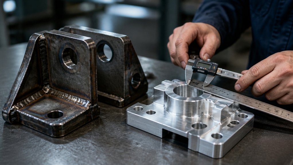
Fabrication forms or joins metal, while machining removes metal to create features; the better choice depends on the part’s shape, interfaces, material, and required accuracy. Fabrication includes cutting, bending, welding, and assembly. For example, a welded frame made from A36 carbon-steel plate may need checks for distortion, fit-up, and weld access. Distortion is shape change caused by uneven heating and cooling. Springback is the partial return of bent metal toward its original shape after the forming force is removed.
Machining uses cutting tools to make features such as holes, slots, and flat faces. A machined part may be made from 6061-T6 aluminum plate, for example. Its dimensions can vary with tool wear, workholding, machine condition, and heat. Workholding means the clamps or fixtures that hold a part during cutting. Releasing those forces can let a thin or unevenly cut part shift.
When briefing a supplier, identify the material and grade, stock thickness, critical dimensions, datum features (the reference surfaces used for measurement), and required finish. State which faces or holes must align with mating parts. Ask how the supplier will inspect those features and report results. Fabrication often suits large formed structures and welded assemblies; machining often suits precise interfaces. A hybrid part may use both. The choice depends on geometry, fit, production quantity, inspection needs, and the cost drivers of setup, material use, and processing time.
What Tolerance Ranges Can Each Process Hold?
Tolerance depends on the process, material, part size, geometry, setup and inspection method. For sheet-metal work, distinguish cut dimensions from bend dimensions: the drawing, material thickness and bend geometry affect what a fabricator can hold. Welded assemblies can shift as the metal heats and cools, so fixture design and the inspection plan matter.
For CNC machining, the achievable tolerance depends on the feature, material, machine setup and measurement method. A tolerance is the permitted variation from a stated dimension; don’t assign a tight tolerance to every feature without a functional reason. Tight limits can require more setups and inspection, and variation can accumulate between features.
On the drawing, identify critical dimensions and specify the required tolerance for each. State the material grade and thickness, define datums (reference surfaces or features used for measurement), and identify how the part will be inspected. Ask the supplier to confirm capability against the drawing before production. Use an inspection report to check that the finished parts meet the specified limits.
How Do Materials and Part Design Affect Tolerances?
Material, geometry, and surface finish affect the tolerances a metal part can hold by influencing how it moves during cutting and how it’s measured. For example, heat and cutting forces can distort aluminum during milling, while harder alloys can resist cutting forces but wear tools faster. The result depends on the alloy, its temper (heat-treated condition), stock thickness, and machining process.
Part shape can also make dimensions harder to control. Thin walls may flex under a milling cutter, and long unsupported features may vibrate; deep cavities can limit tool and fixture access. A drawing can help prevent these problems by identifying critical dimensions, specifying the material and thickness, and showing where ribs or supports are acceptable.
Surface finish is the texture left by machining or another process. Peaks and valleys on a rough surface can affect measurement readings and how mating parts fit. Specify a finish based on the part’s function and measurement method, and agree on how critical dimensions will be checked. The appropriate tolerances depend on the material, part geometry, process, and intended fit.
How Do You Specify a Realistic Tolerance?
Specify a realistic tolerance by starting with the part’s function and the limits of the chosen manufacturing process. A tolerance is the permitted variation in a dimension. Tighten it only where variation could affect fit, movement, assembly, or performance.
For example, a hole that locates a machined steel pin may need closer control than an outside edge on a laser-cut sheet-metal cover. The right limits depend on the material and grade, thickness, part geometry, process, production quantity, and how the part will be assembled. Ask the fabricator to confirm that the proposed limits are achievable and measurable for the specified process, such as laser cutting, press-brake forming, machining, or welding.
Tighter tolerances can require more setup, specialized tooling, extra machining or inspection, and may increase scrap risk. Use standard tolerances where they meet the part’s needs, and explain any tighter requirement on the drawing. Define datums—the reference points or surfaces used to locate and measure features—and geometric controls when relationships between features matter. Avoid dimension chains that can accumulate variation. Review the drawing with the fabricator before release, including how critical dimensions will be inspected and whether the method can be repeated consistently in production.
Frequently Asked Questions
How Do Tighter Tolerances Affect Manufacturing Costs?
Tighter tolerances usually increase manufacturing costs because they can require slower machining, more capable equipment, additional inspection, and tighter control of material and setup. The effect depends on the process, alloy, part geometry, production volume, and how the part fits into its assembly.
For a CNC-milled aluminum bracket, for example, a narrow tolerance on a hole may require a finishing pass and measurement with a bore gauge rather than a routine check with calipers. A tolerance is the permitted variation from a specified dimension; a process capability study checks whether a production process can hold that range consistently. Ask the supplier to identify critical dimensions and explain how each will be measured.
Tight limits can also raise scrap and rework if normal variation in cutting, forming, welding, or material condition pushes parts out of specification. In a welded steel frame, heat can distort dimensions, so a tight requirement may call for a different sequence, fixture, or post-weld machining. Tolerance stack-up is the combined effect of dimensional variation across assembled parts; review the assembly to see whether every component needs a tight limit or only the features that control fit and function.
When Should a Part Be Inspected During Production?
Inspect a metal part at setup, after its first production operation, whenever the process or material changes, and before final release. These checks can catch a setup error or a developing defect before more parts are made or more work is added.
At setup, verify the drawing revision, material grade and thickness, tooling, and measurement method. After the first operation, check the features that operation could affect: for example, inspect bend angle and flange dimensions after press-brake forming, or hole position and edge condition after laser cutting. A fabrication tolerance is the allowed variation in a formed or assembled feature; a machining tolerance is the allowed variation in a feature made by cutting, drilling, or milling. Use the tolerances on the drawing rather than assuming a general limit.
Repeat checks when a tool, machine setting, material batch, or process changes, because each can affect part dimensions or quality. Before release, verify critical dimensions, required finish, and any specified inspection records. The inspection plan should reflect the part’s function, drawing requirements, material, process, and consequences of a defect.
What Inspection Methods Verify Dimensional Accuracy?
Dimensional accuracy is checked with measuring tools suited to each feature, such as calipers, micrometers, height gauges, coordinate-measuring machines (CMMs), and optical comparators. The right method depends on the part’s geometry, material, required tolerance, and inspection plan.
Calipers measure outside, inside, and depth dimensions. Micrometers measure thickness or diameter where closer control is needed. A height gauge checks vertical distances from a reference surface, while a CMM uses a probe to record points across a part and compare them with a digital model or drawing.
An optical comparator projects a magnified outline onto a screen for checking profiles, angles, and small features without touching the part. For sheet-metal parts, inspection may also include checking hole locations, bend angles, and overall flatness; the drawing should identify the datums, or reference features, used for those checks.
The inspection report should state the measured values and identify the drawing revision and measuring method. Compare each result with the drawing’s specified limits, and confirm that the tool’s resolution and calibration are suitable for the tolerance being checked.
Can Suppliers Certify That Parts Meet Specified Tolerances?
Yes. A supplier can certify that a metal part meets specified tolerances through an inspection report or a certificate of conformity, a document stating that the supplied part meets the order’s requirements.
The purchase order or drawing should identify the dimensions to inspect, the required tolerances, and the measurement method. A tolerance is the permitted variation from a specified dimension. For a laser-cut steel plate, for example, the order should state the steel grade, thickness, critical dimensions, and any applicable drawing notes. The required checks depend on the part’s material, manufacturing process, geometry, and intended use.
Ask for measurement records that link each result to the part or production batch. The records should identify the measuring equipment and show that it is calibrated, meaning checked against a recognized reference. For critical features, specify whether the supplier must inspect every part or a sample, and agree on the sampling method before production.
A supplier audit can help verify inspection procedures, equipment controls, and record keeping. ISO 9001 sets requirements for quality-management systems; it does not by itself certify that a particular part meets its drawing.
What Should I Do if a Finished Part Is Out of Tolerance?
Quarantine the part and do not install or ship it until the discrepancy is resolved. An out-of-tolerance part has one or more measured features outside the limits on the approved drawing or purchase specification.
Recheck the feature with a calibrated measuring tool suited to its size and geometry, such as a micrometer for thickness or a coordinate-measuring machine for complex features. Confirm the drawing revision, units, datum references (the points or surfaces used to locate measurements), and any stated inspection method. Record the readings and compare them with the specified limits; do not assume a process capability or material variation makes the part acceptable.
Notify the supplier with the drawing revision, affected feature, measurement method, and inspection results. Ask for a documented root-cause analysis, which identifies why the failure occurred, and corrective action to prevent recurrence. Request replacement or rework only if the proposed repair is permitted by the drawing, material requirements, and applicable code or customer approval. Welding, machining, or forming a part after fabrication can change its dimensions or material condition, so acceptance depends on the part’s function and specification. Keep the part segregated until an authorized buyer, engineer, or inspector approves its disposition.